Right inverter–module pairing turns nameplate watts into dependable kilowatt‑hours. Done well, it limits trips, squeezes more energy from each string, and protects modules and batteries. This piece gives practical rules for solar inverter compatibility, inverter pairing, and module reliability, backed by field data and standards.

Why pairing matters for reliability and yield
Availability losses often start with preventable issues: nuisance trips, mismatch, and poor temperature margins. According to Solar Energy Perspectives (IEA), well‑designed plants sustain performance ratios around 80%–90%, and inverters can trip on ground or arc faults if design or settings are off. Reducing false trips and improving protection coordination raises uptime.
Mismatched modules waste energy. Module‑level power electronics (MLPE) or smarter string design fix it. The U.S. DOE EERE success story on parallel wiring and a DC converter shows how per‑module control can lift PV module performance by allowing each module to operate independently—valuable under shade or soiling.
System components live together. PV module performance, inverter‑module synergy, and the balance‑of‑system all shape the result, a point reinforced across the IEA Technology Roadmap – Solar PV: modules, inverters, protection, and structure must be sized and coordinated as a whole.
Electrical matching fundamentals
Cold‑weather voltage limits (Voc)
Open‑circuit voltage rises as temperature drops. Check the coldest module temperature at site (use historical Tmin and add a safety margin). Compute string Voc at Tmin using the module’s Voc temperature coefficient. Keep below the inverter’s max DC voltage, with a buffer.
- Rule of thumb: cold Voc string ≤ 90%–95% of inverter max DC.
- Use module datasheet Voc (STC) and temperature coefficient (e.g., −0.28%/°C for Voc on many n‑type modules) to estimate cold Voc.
MPPT window and hot Vmp
The inverter’s MPPT window must cover the string’s operating voltage across seasons. As cells heat, Vmp drops. Verify the hot Vmp string stays above the MPPT lower bound and the cold Vmp stays below the MPPT upper bound. Sites with high module temperatures or long strings can fall out of range.
- Check: Vmp_hot string ≥ MPPT_min; Vmp_cold string ≤ MPPT_max.
- High irradiance and heat can push current up while voltage falls; both limits matter.
Current, strings in parallel, and input limits
Short‑circuit current (Isc) rises slightly in cold, bright conditions and with bifacial gain. The total current per MPPT equals Isc × strings in parallel (consider a factor for irradiance spikes). Keep below the MPPT input and connector ratings, and align string fusing with wire ampacity.
- Combine strings per MPPT so total current ≤ MPPT limit with margin.
- Respect connector and fuse ratings; many faults trace back to small wiring mistakes.
Worked mini‑example
Assume a 41.0 V Voc, 34.0 V Vmp, Isc 11 A module; Voc tempco −0.28%/°C. Inverter: max DC 1100 V, MPPT 200–850 V, MPPT input current 30 A.
| Scenario | Tmin | Cold Voc/module | Max modules/string | Hot Vmp/string (est.) | MPPT check | Parallel strings | Current check |
|---|---|---|---|---|---|---|---|
| Temperate | −10°C | ~45.0 V | 24 (1100/45) | 23×~29.2 ≈ 673 V | 200–850 V: OK | 2 | 2×11=22 A ≤ 30 A: OK |
| Cold | −25°C | ~46.7 V | 23 (1100/46.7) | 22×~29.2 ≈ 642 V | 200–850 V: OK | 2 | 22 A ≤ 30 A: OK |
Pick 22–23 modules per string here to keep margin on cold Voc, and 2 strings per MPPT to stay under current limits.
DC:AC ratio (ILR) and clipping
Inverter‑loading ratio (ILR, or DC:AC ratio) shapes energy capture and clipping. A modest oversize of DC helps harvest more early/late energy and during cloudy periods. Too much oversize invites frequent clipping on clear cool days and stresses BOS thermally.
- Common ILR starting points: 1.15–1.30 for fixed‑tilt; 1.25–1.45 for single‑axis tracker (site‑specific).
- Colder, high‑irradiance sites need lower ILR; hot sites tolerate higher ILR due to lower voltage and more thermal derating.
| ILR | Typical annual clipping | Notes |
|---|---|---|
| 1.10 | ~0%–1% | Low clipping; may leave energy on the table off‑peak |
| 1.30 | ~2%–4% | Balanced for many sites; higher net yield |
| 1.50 | ~5%–8% | Check thermal limits and cable ratings carefully |
IEA notes that tracking and better BOS can raise energy yield—tilt/tracking settings influence the optimal ILR by shifting irradiance profiles over the day. Always validate with site TMY data and the module’s temperature behavior.
Designing for fewer trips and longer life
Arc‑faults, ground‑faults, and false trips
False trips cost energy. According to the IEA overview, improving inverters and system design to eliminate false trips reduces availability loss. Set protection thresholds per manufacturer guidance, keep connectors clean and fully seated, and avoid mixed connector brands. Verify ground‑fault detection with proper bonding and insulation tests.
Thermal management and altitude
Inverters derate with temperature and thin air. Provide shade, airflow, and spacing. At altitude, lower air density weakens convective cooling; check derating curves. Keep cabling and combiner enclosures within thermal limits.
MPPT channeling and string symmetry
Assign strings with similar irradiance and orientation to the same MPPT. Mixing shaded and unshaded strings on one MPPT reduces PV module performance. Use multiple MPPTs or MLPE to isolate mismatch.
Quality assurance and BOS discipline
The IEA roadmap underscores BOS quality as a reliability lever. Torque specs, UV‑rated ties, bending radius, and correct wire gauges prevent intermittent faults.
Special cases: MLPE, hybrid ESS, and bifacial nuance
MLPE for shade and complex roofs
Module‑level devices reduce mismatch losses and improve partial‑shade energy. The DOE case shows per‑module converters enabling parallel wiring with higher DC bus voltage, improving yield and lowering some material costs. On large plants, compare MLPE benefits against added points of failure and O&M.
Hybrid/off‑grid with LiFePO4 storage
For hybrid inverters paired with LiFePO4, align charge voltages and C‑rates with battery specs. Typical 16‑cell LiFePO4 banks sit near 51.2 V nominal with bulk/absorb in the ~55–57.6 V range depending on manufacturer. Verify battery communication protocols, low‑temperature charge limits, and inverter‑charger current limits. This protects cycle life and keeps trips down.
Bifacial modules
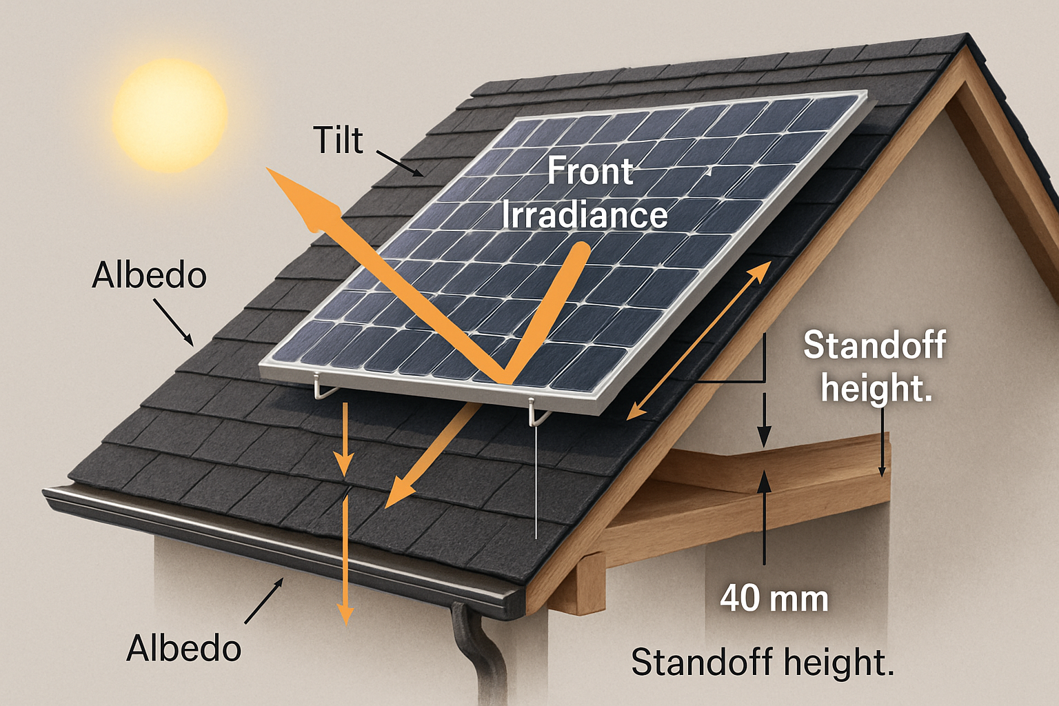
Bifacial gain lifts current more than voltage, increasing MPPT input current demands. Recheck current limits per MPPT and string fusing, and revisit ILR to control clipping on clear, reflective days. For context on energy yield drivers, see IEA’s energy yield discussion.
Field checklist you can apply today
- Confirm environmental data: Tmin, Tmax, altitude, soiling, reflectivity.
- Cold Voc margin: keep string Voc at Tmin ≤ 90%–95% of inverter max DC.
- MPPT coverage: string Vmp stays inside MPPT window across seasonal temps.
- Current safety: strings per MPPT × Isc (with margin) ≤ MPPT limit; select correct fuses.
- Pick ILR from site data, then simulate clipping and inverter thermal limits.
- Group strings per MPPT by orientation and shading; add MLPE if mismatch is unavoidable.
- Document protection settings; test arc‑fault/ground‑fault behavior during commissioning.
- Plan ventilation and service access; check derating at ambient extremes and altitude.
Short case snapshot
800 kWdc rooftop, fixed tilt, warm climate. Module Voc 41 V, Vmp 34 V, Voc tempco −0.28%/°C. Tmin 0°C. Inverter MPPT 200–800 V, max DC 1100 V, MPPT current 26 A. Design selects 22 modules per string (cold Voc ~45 V × 22 = 990 V), Vmp_hot string ~640 V, two strings per MPPT (22 A ≤ 26 A), ILR 1.25. Result: balanced clipping (~3%), solid MPPT coverage, and low nuisance trips. This aligns with practices highlighted across DOE Solar Energy resources.
Sourcing, standards, and further reading
- IEA – Solar Energy Perspectives: performance ratio ranges, availability, and BOS context.
- IEA – Technology Roadmap: Solar Photovoltaic Energy: system integration and BOS focus.
- IRENA: market and technical reports that inform PV selection and risk control.
- DOE EERE – Per‑module converter success story: parallel wiring and module independence.
- DOE – Solar Energy: policies, R&D progress, and technology primers.
Disclaimer: This content is for technical education, not legal, code, or investment advice. Verify local grid codes and product manuals.
FAQ
How do I choose a safe DC:AC ratio for my site?
Start with 1.15–1.30 for fixed tilt, 1.25–1.45 for trackers, then run site simulations. Cooler, high‑irradiance sites benefit from lower ILR to control clipping and DC voltage peaks.
What margin should I keep below the inverter’s max DC voltage?
Target cold string Voc ≤ 90%–95% of the inverter limit to account for measurement uncertainty, weather outliers, and manufacturing tolerances.
Do I need MLPE on every project?
Use MLPE where shading, multi‑orientation arrays, or complex roofs drive mismatch. For uniform utility‑scale layouts, well‑planned stringing and multiple MPPTs can be enough.
How does battery storage affect inverter pairing?
Hybrid systems need inverter‑charger settings that match the battery’s charge profile and current limits. For LiFePO4, verify bulk/absorb voltage, low‑temperature charging rules, and communication protocols.
What is the impact of altitude on inverter selection?
Higher altitude reduces cooling capacity. Check manufacturer derating curves and ensure mounting and airflow meet the required thermal performance.


Leave a comment
All comments are moderated before being published.
This site is protected by hCaptcha and the hCaptcha Privacy Policy and Terms of Service apply.