Perspective: From my experience auditing residential and commercial PV projects, nothing creates more confusion than how to handle grounding, bonding, and isolation at the inverter. These details decide whether your system is safe, code-compliant, and insurable. Below I outline what I’ve seen work in practice, and how global standards frame the discussion.
Core Principles: Grounding, Bonding, Isolation
- Grounding gives fault currents a path to earth so protective devices trip reliably.
- Bonding ties all metallic components together so no dangerous voltage difference exists between racks, frames, or chassis.
- Isolation keeps certain conductors intentionally floating, often in transformerless inverter designs, with fault detection electronics providing protection.
On the DC Side: Solar Array and Wiring
Frames and racking must always be bonded to the equipment grounding conductor. I’ve seen cases where a single missed bonding jumper left an array floating at 200 V—hazardous until corrected. For conductors:
- Negative-grounded arrays were standard for years.
- Positive-grounded designs were tied to older thin-film modules.
- Ungrounded or floating is now common with transformerless inverters, which rely on ground-fault detection interrupters (GFDI) for safety.
Always confirm the inverter’s required scheme. Mismatched grounding leads to warranty voids and potential hazards.
On the AC Side: Integration with the Home or Grid
The AC side connects inverter output to the main service panel. The chassis must be grounded through the equipment grounding conductor. The key rule involves the neutral-to-ground bond:
| System Type | Bond Location | Why |
|---|---|---|
| Grid-Tied | Main Service Panel | Only one bond point avoids parallel paths and GFCI issues. |
| Off-Grid / Backup | Inside inverter or subpanel | The inverter becomes the source and must set a stable reference. |
New Considerations: Storage Integration
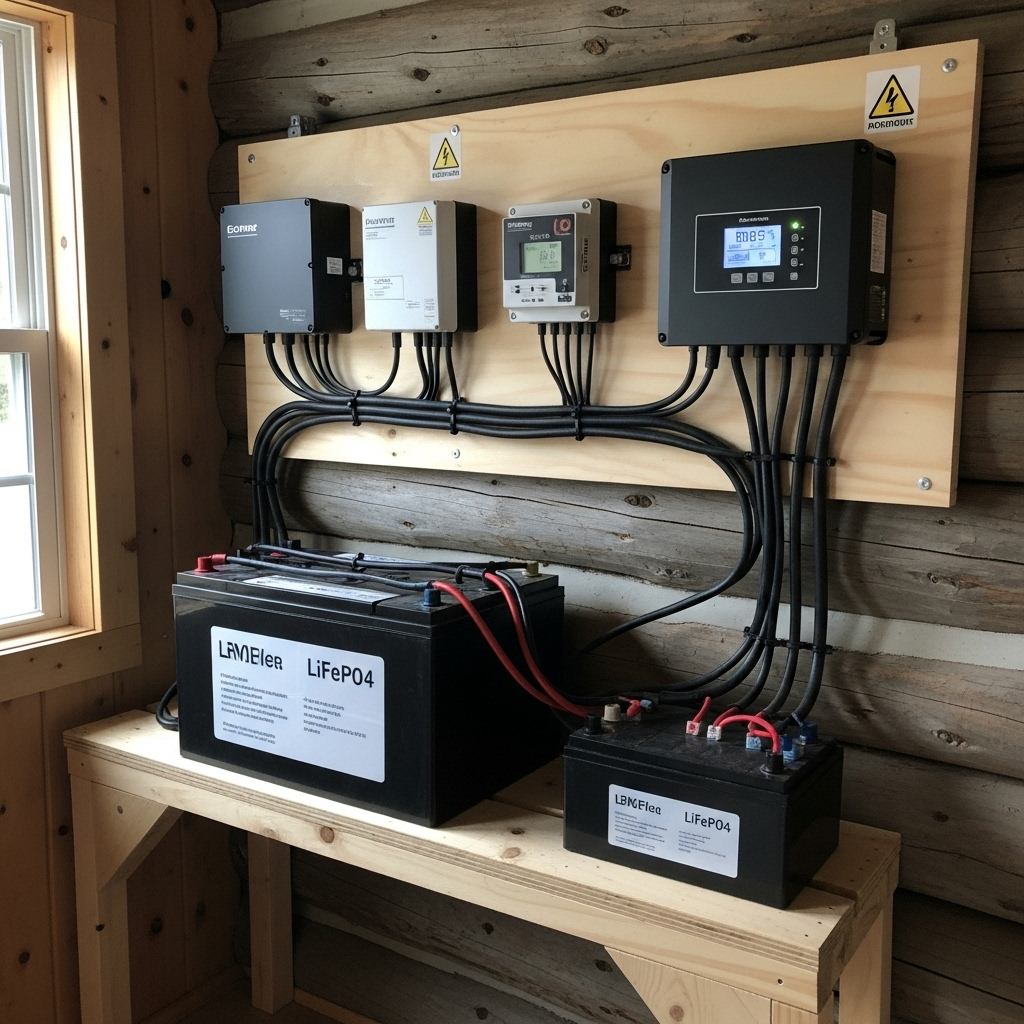
Adding a battery complicates grounding. The rack must be bonded, but the inverter and BMS coordinate to ensure fault detection. In one project I reviewed, improper bonding created nuisance trips during grid-support functions. Updating the wiring to match the inverter-BMS scheme resolved the issue and restored compliance with IEEE and IEA integration guidance (IEA reference).
Checklist: How I Verify Safety
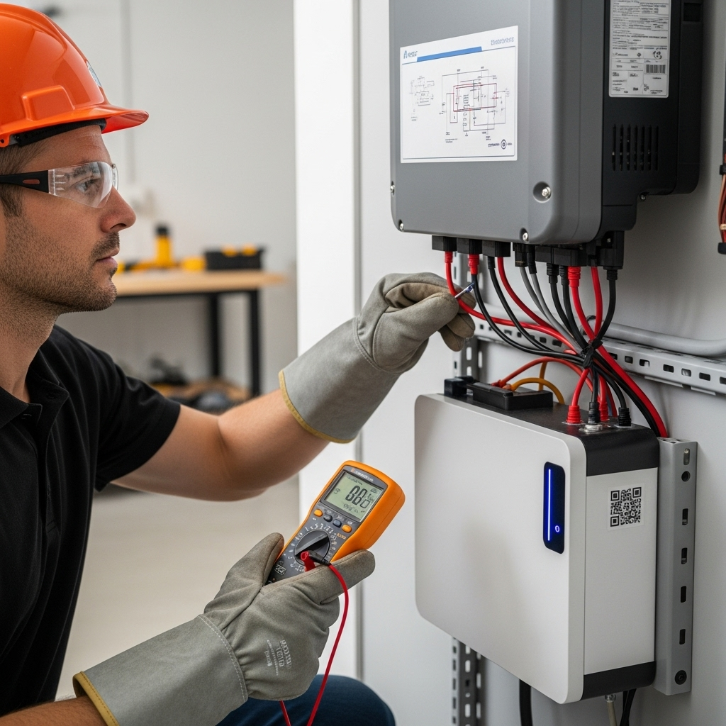
- Inspect all frame bonds and verify continuity with a multimeter.
- Confirm the DC grounding scheme matches the inverter manual.
- Check inverter chassis ground to the service panel bus bar.
- Identify the single neutral-to-ground bond location.
- Run a simulated fault test to confirm breakers or RCDs trip as expected.
Why It Matters for Bankability
Lenders and insurers increasingly review grounding and bonding documentation. A poorly wired bond is not just unsafe—it can void insurance or interconnection approval. In my advisory work, showing test results and as-built diagrams has been decisive in keeping projects financeable.
Closing Thoughts
Grounding, bonding, and isolation are not optional details—they are the spine of a safe PV installation. Done correctly, they prevent shocks, fires, and downtime. Done poorly, they jeopardize safety and project economics. Following inverter manuals, applying NEC/IEC guidance, and validating connections on-site ensures both reliability and bankability.
Disclaimer: Informational only. Always consult inverter documentation, electrical codes, and licensed professionals before installation.


Leave a comment
All comments are moderated before being published.
This site is protected by hCaptcha and the hCaptcha Privacy Policy and Terms of Service apply.