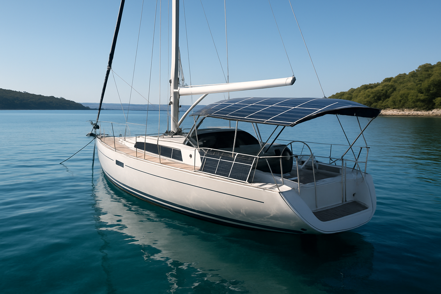
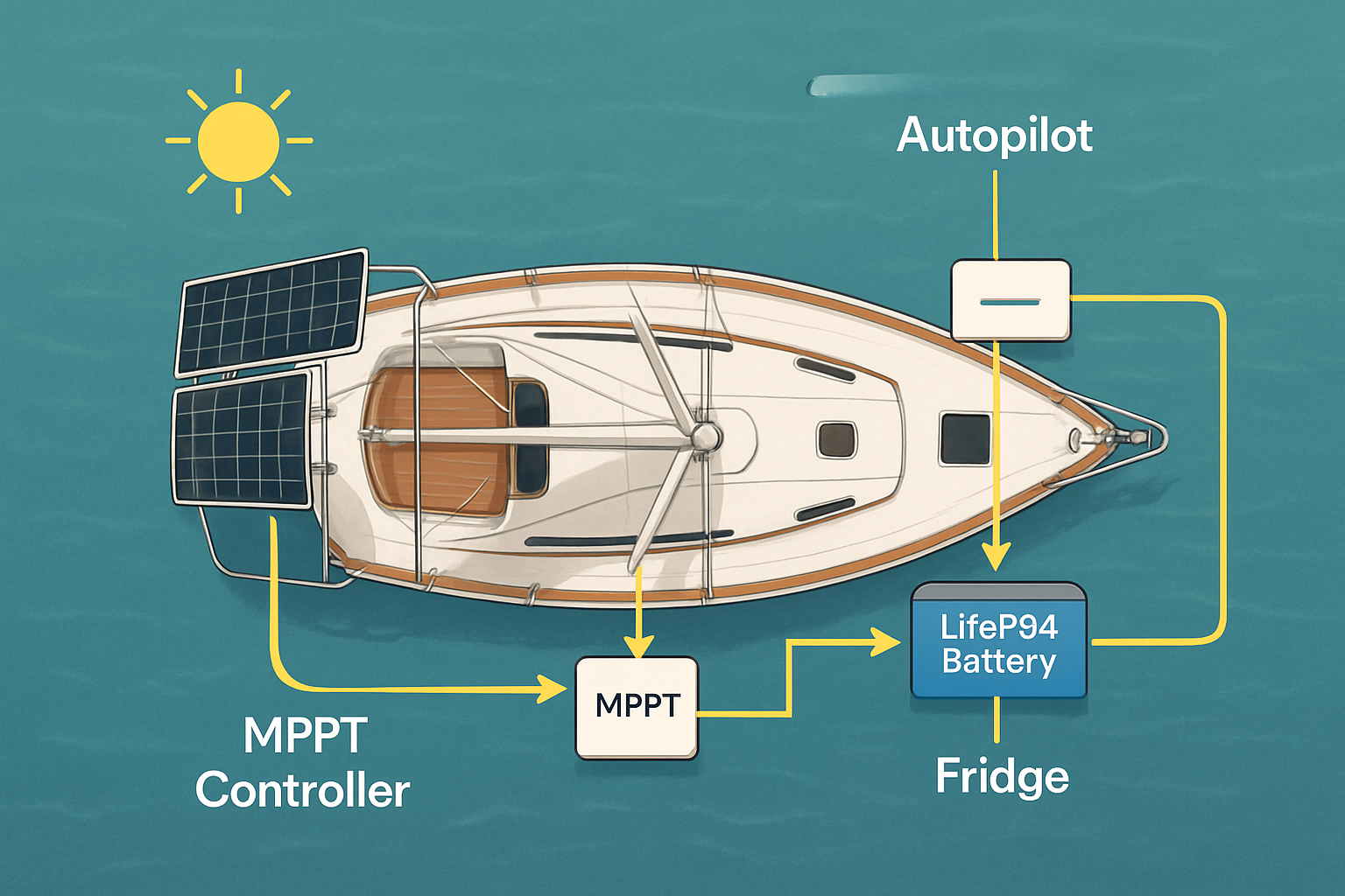
This blueprint shows how to architect a dependable marine solar power system for boats. You get a clean layout, component specs, wiring protections, and commissioning steps that keep lights, instruments, autopilot, and a fridge running without constant engine time. The focus is simple: practical Marine Solar Panels, the right Boat Solar Inverters, and a LiFePO4 Battery Marine bank that fits your space and use.

A clean system architecture that works at sea
Keep the design simple and serviceable. Separate DC and AC paths, fuse everything close to the source, and leave space to cool electronics. A proven layout includes:
- PV array to MPPT charge controller, then to a LiFePO4 house bank.
- 12 V or 24 V DC house bus feeding nav gear, lighting, pumps, and refrigeration.
- Inverter or inverter‑charger feeding a small AC panel for outlets and select loads.
- Optional shore or genset input through a transfer switch or inverter‑charger.
Yield depends on sun exposure, heat, angle, and shading. Global horizontal irradiance (GHI) drives daily Wh. Maps referenced by IRENA’s 2022 Year in Review show high GHI in many subtropical waters. On a flat marine deck with some shading, daily production often falls in the 2.5–4.0 kWh/kWp range in fair weather. That range tracks fundamental PV behavior summarized in the IEA’s Solar Energy Perspectives.
| Subsystem | Blueprint spec | Notes |
|---|---|---|
| PV Array | 200–1200 W, 18–40 Vmp per string | Series for voltage, parallel for shade resilience; include blocking diodes on parallel strings |
| MPPT | Current rating ≥ 1.25 × array Isc | Marine‑grade terminals, temp sensor to battery negative, short absorb for LiFePO4 |
| LiFePO4 Bank | 12 V or 24 V, 100–600 Ah | Internal BMS with low‑temp charge cutoff; mount low and ventilated |
| Inverter | Pure sine, 1–3 kVA, surge ≥ 2× | Low idle draw, RCD/GFCI friendly, programmable neutral bonding |
| Protection | Class‑T on battery, MRBF at branch, DC/AC breakers | Fuse within 18–20 cm of source; aim for ≤3% DC voltage drop |
| Monitoring | Shunt‑based SOC + PV yield counter | Log daily Wh to spot issues early |
| Integration | Shore/genset via transfer | Earth leakage protection and correct neutral handling at dock |
Marine Solar Panels: selection, placement, and wiring
Panel choice and placement
Use rigid framed modules on arches or davits for airflow and lifespan. Flexible modules suit curved biminis but run hotter, which trims output. Keep shadows from backstays, antennas, and booms off cells. Even thin lines cut current in a series string. Parallel strings with independent MPPT tracking reduce shade losses.
Realistic yield hinges on sun resource and deck conditions. GHI datasets highlighted by IRENA and principles in the IEA’s Solar Energy Perspectives show strong production in tropical belts, with lower output at higher latitudes and in winter. Expect lower kWh per kWp on flat, un‑tilted marine mounts compared with land arrays.
Wiring tactics that save watts
- Target ≤3% voltage drop from panels to MPPT and MPPT to battery. Upsize cable or shorten runs.
- Use tinned copper boat cable, heat‑shrink crimps, and IP67 glands. Seal balsa or foam cores before drilling.
- Keep PV leads away from compasses and audio. Twist positive/negative pairs and add ferrites at the MPPT to reduce EMI.
Boat Solar Inverters: choices, settings, and safety
Pick a pure sine inverter sized for continuous and surge loads. Look hard at idle draw. A unit that sips 10–15 W at rest can save hundreds of Wh per day at anchor.
Smart functions and standards
Grid‑support features like voltage regulation and frequency‑watt came from national efforts to standardize testing. According to the U.S. Department of Energy’s EERE Success Story—Smart Solar Inverters, standardized tests now cover voltage regulation, ride‑through, and modulated power. While boats do not grid‑tie at sea, the same control quality signals robust design and stable AC for sensitive electronics.
Inverter checklist for boats
| Feature | Why it matters on a boat | Target spec |
|---|---|---|
| Waveform & THD | Pumps, chargers, and tools run cooler | Pure sine, THD ≤ 3–5% |
| Surge | Compressor start without brownout | ≥ 2× for ≥ 2 s |
| Idle/search mode | Lower parasitic draw at anchor | Idle ≤ 15 W, search ≤ 5 W |
| Transfer switch | Seamless shore changeover | Transfer ≤ 20 ms, correct neutral handling |
| EMI | Reduce interference with VHF, AIS | Good filtering; ferrites on AC/DC leads |
| RCD/GFCI behavior | Safety at dock | Compatible with 30 mA RCD, no nuisance trips |
Standardized interconnection ideas can cut install complexity. The DOE’s EERE Success Story—Connection Without the Costs shows how purpose‑built interfaces reduce labor and errors on land systems. On boats, use labeled sub‑panels, clear transfer labeling, and locking connectors to achieve the same clarity.
LiFePO4 on boats: settings, protection, and integration
LiFePO4 shines for marine use. High cycle life, fast charge acceptance, and usable depth of discharge support compact banks. Size for daily loads plus a buffer, then set charge profiles to match the chemistry. IRENA notes that energy storage planning depends on total load, efficiency, days of autonomy, and allowable depth of discharge. The same logic applies afloat.
Baseline charge profile (12 V nominal)
- Bulk/Absorb: 14.2–14.4 V; Absorb time short (10–20 min) once current tapers.
- Float: 13.4–13.6 V, or disable float for storage.
- Temperature compensation: off or minimal for LiFePO4; follow battery maker guidance.
Protection features that matter
- BMS with low‑temperature charge cutoff (~0–5°C). Cold charging risks plating.
- Class‑T main fuse sized to inverter surge and total DC loads.
- Main battery switch, plus MRBF fuses at branch circuits.
- Rigid battery restraints and ventilation space around electronics.
EMI, safety, and corrosion control
- Run AC and DC in separate conduits. Cross at 90° if paths intersect.
- Bond grounds correctly. Avoid ground loops by using a single negative bus point.
- Use drip loops and strain relief. Keep electronics out of damp lockers.
- Label polarity at every device. Verify with a meter before final landings.
Smart inverter behaviors and inverter‑based resources are a key part of modern power systems, a theme also tracked by the IEA’s Energy and AI work. Stable power electronics reduce nuisance resets in choppy seas.
Production expectations and shade tactics
On‑deck arrays sit flat, heat up, and see intermittent shadows. Expect lower capacity factors than ideal land mounts. Data‑driven planning starts with GHI and temperature inputs the way national studies do, such as the IEA’s Solar Energy Perspectives and IRENA’s resource briefs. Combine this with your boat’s shade map. Favor parallel strings and multiple MPPTs if arches, radars, or sails cross the sun path.
Use‑case matrix: quick blueprint picks
| Use case | Marine Solar Panels | LiFePO4 Battery Marine | Boat Solar Inverters | Notes |
|---|---|---|---|---|
| Day sailor, electronics + lights | 100–200 W | 12 V 50–100 Ah | None or 300–600 VA | Run DC loads; keep AC minimal |
| Coastal cruiser, fridge + instruments | 300–600 W | 12 V 150–300 Ah | 1–2 kVA | Idle draw matters; search mode helps |
| Liveaboard, fridge + work laptop | 600–1000 W | 12/24 V 300–500 Ah | 2–3 kVA inverter‑charger | Fast transfer at dock; shore RCD friendly |
Commissioning checklist
- Torque and label every terminal. Photograph final landings for future service.
- Program MPPT for LiFePO4 values. Set short absorb and conservative float.
- Program inverter low‑voltage cutout to protect the bank.
- Calibrate the shunt monitor. Log baseline PV Wh on a sunny day.
- Do a load test at anchor: fridge, instruments, and a kettle surge through the inverter.
Evidence and data points that inform this blueprint
- PV conversion and inverter roles are core to stable AC power, summarized by the U.S. DOE’s Smart Solar Inverters brief, which also notes standardized testing for advanced controls.
- Battery sizing depends on load, system efficiency, autonomy, and DOD per IRENA’s healthcare electrification report; these factors translate directly to boats.
- GHI maps and climate‑driven resource patterns in IRENA’s Year in Review support realistic production ranges for flat marine arrays.
- PV performance fundamentals and the impact of temperature and angle are discussed in the IEA’s Solar Energy Perspectives, grounding expectations for on‑deck installations.
- Purpose‑built interconnection hardware reduces install complexity and cost in land systems, per the DOE’s Connection Without the Costs. The same principle guides neat, serviceable marine wiring.
Putting it to use
Start with a clear layout, then match a modest array to your daily DC loads, and pick an inverter that sips at idle. Set LiFePO4 charge limits correctly. Protect every circuit. That sequence raises uptime at anchor and trims fuel. Store your baseline yield and consumption so you can spot trouble fast.
Safety and compliance note: This content is for information only and not professional, electrical, or legal advice. Hire a qualified marine electrician for final design and inspection.
FAQ
Can Marine Solar Panels keep a fridge and instruments running?
Yes, with enough array area and a right‑sized LiFePO4 bank. Fridges need steady Wh per day. A 400–600 W array with a 12 V 200–300 Ah bank covers a small fridge and electronics in fair conditions, with margin for cloudy spells.
Do I need an inverter‑charger or a separate inverter?
An inverter‑charger simplifies shore/genset use with built‑in transfer and charging. A stand‑alone inverter suits DC‑focused boats that rarely plug in. Check idle draw, surge, and RCD behavior in both cases.
Should I choose 12 V or 24 V?
Stay 12 V for small boats and legacy gear. Choose 24 V for higher power inverters to halve current and cable size. Step down to 12 V loads with DC‑DC converters.
How do I protect LiFePO4 in cold weather?
Use a BMS with low‑temp charge cutoff and a charger that respects it. Charge above freezing. Store at partial SOC in cool, dry spaces with parasitic loads removed.
What reduces shade losses on boats?
Mount panels where rig shadows are minimal, use parallel strings with independent MPPTs, keep the deck wiring short and thick, and keep panels cool and clean.


Leave a comment
All comments are moderated before being published.
This site is protected by hCaptcha and the hCaptcha Privacy Policy and Terms of Service apply.