Building resilient off-grid microgrids requires precise sizing of three critical components: photovoltaic arrays, inverters, and energy storage systems. Unlike simple solar installations, microgrids must maintain stable power during grid outages while managing complex load profiles and ensuring long-term energy independence.

The emergence of grid-forming inverter technologies has revolutionized microgrid capabilities. These systems can operate completely independent of conventional synchronous generation, providing all necessary grid services through advanced control algorithms.
Understanding Microgrid Load Dynamics
Microgrid sizing begins with comprehensive load analysis that extends beyond simple energy consumption calculations. Critical facilities like hospitals, emergency services, and communication systems require continuous power with specific quality parameters.
Peak Demand vs Continuous Load
Your microgrid must handle both steady-state loads and sudden demand spikes. Motor starting currents can reach 6-8 times nominal values, while HVAC systems create significant load variations throughout the day. Calculate peak demand using the formula:
Peak Demand (kW) = Σ(Connected Load × Demand Factor × Diversity Factor)
Where demand factors typically range from 0.6-0.8 for residential loads and 0.7-0.9 for commercial facilities. Diversity factors account for non-simultaneous operation, usually 0.8-0.95 for mixed loads.
Load Classification and Priority
Categorize loads into three tiers:
- Critical loads: Life safety, security, communications (100% availability required)
- Essential loads: Lighting, basic HVAC, refrigeration (95% availability target)
- Optional loads: Non-essential equipment (can be shed during emergencies)
This classification directly impacts storage sizing, as critical loads determine minimum battery capacity requirements during extended outages.
PV Array Sizing for Microgrid Applications
Microgrid PV sizing differs significantly from grid-tied systems. You must account for islanding requirements, voltage regulation, and seasonal variations without grid support.
Energy Balance Calculations
Calculate required PV capacity using the modified energy balance equation:
PV Array Size (kW) = Daily Load (kWh) × 1.25 / (Peak Sun Hours × System Efficiency × Availability Factor)
The 1.25 multiplier accounts for battery charging inefficiencies and system losses specific to islanded operation. System efficiency typically ranges from 0.75-0.85 for well-designed microgrids, lower than grid-tied systems due to additional conversion stages.
| Location | Peak Sun Hours (Annual Average) | Winter Minimum | Sizing Multiplier |
|---|---|---|---|
| Arizona | 6.8 | 4.2 | 1.6 |
| Florida | 5.4 | 3.8 | 1.4 |
| New York | 4.2 | 2.1 | 2.0 |
| Alaska | 3.1 | 0.8 | 3.9 |
Voltage Regulation Requirements
Microgrids must maintain voltage within ±5% during all operating conditions. Size your PV array to provide adequate reactive power support, typically requiring 10-15% oversizing compared to pure energy calculations.
For systems above 100kW, implement multiple PV subarrays with independent maximum power point tracking to maintain stable output during partial shading or equipment failures.
Inverter Sizing and Grid-Forming Capabilities
Inverter selection represents the most critical component decision in microgrid design. Unlike grid-following inverters, grid-forming inverters must establish and maintain grid parameters independently.
Power Rating Calculations
Size inverters using the following methodology:
Inverter Rating (kVA) = Peak Load (kW) / Power Factor × Safety Factor × Temperature Derating
Safety factors should be 1.2-1.3 for critical applications, while temperature derating ranges from 0.9-0.95 depending on installation environment. For motor loads, add 25-30% capacity to handle starting currents.
Grid-Forming vs Grid-Following
According to IRENA's storage valuation framework, grid-forming inverters provide essential services that grid-following units cannot deliver in islanded operation:
- Voltage and frequency regulation
- Black-start capability
- Fault current contribution
- Load step response
Grid-forming capability typically requires 20-30% higher investment but enables true microgrid functionality with seamless transitions between grid-connected and islanded modes.
Storage System Sizing for Resilience
Energy storage sizing determines your microgrid's autonomy and resilience capabilities. The calculation involves multiple factors beyond simple energy capacity.
Capacity Calculations
Calculate minimum storage capacity using:
Battery Capacity (kWh) = (Critical Load × Autonomy Hours) / (DoD × Inverter Efficiency × Battery Efficiency)
Where:
- Autonomy hours: Minimum 24-72 hours for critical facilities
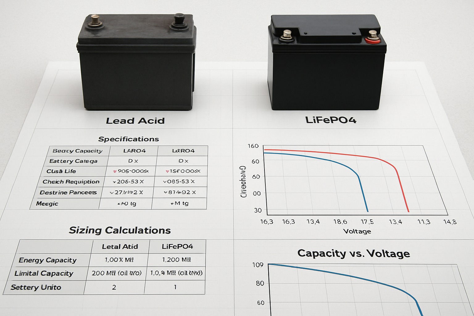
- DoD: 80% for LiFePO4, 50% for lead-acid
- Combined efficiency: 0.85-0.90 for modern systems
Power Rating Requirements
Battery power rating must handle peak loads plus charging requirements:
Battery Power (kW) = Peak Load + (PV Array Size × 0.8)
This ensures simultaneous load serving and battery charging during peak solar production periods.
| Application | Autonomy Hours | Typical Storage Size | Power Rating |
|---|---|---|---|
| Residential | 24-48 | 20-40 kWh | 5-10 kW |
| Commercial | 48-72 | 100-500 kWh | 25-100 kW |
| Critical Facility | 72-168 | 500-2000 kWh | 100-500 kW |
Integration and Control Systems
Modern microgrids require sophisticated control systems to coordinate PV generation, storage operation, and load management. The Department of Energy's microgrid networking tools demonstrate how multiple microgrids can coordinate for enhanced resilience.
Energy Management Systems
Implement hierarchical control with three levels:
- Primary control: Real-time voltage and frequency regulation (milliseconds)
- Secondary control: Set point optimization and power sharing (seconds)
- Tertiary control: Economic dispatch and maintenance scheduling (minutes to hours)
Load Management Strategies
Design automatic load shedding sequences to maintain system stability during supply shortfalls. Critical loads receive priority, while optional loads can be disconnected to preserve battery capacity for essential services.
Validation and Performance Optimization
After initial sizing calculations, validate your design through simulation and real-world testing. Monitor key performance indicators including:
- Energy autonomy achievement (target: 99.5% for critical loads)
- Battery cycle efficiency (should exceed 90% for LiFePO4)
- PV capacity factor (compare to regional benchmarks)
- System availability (target: 99.9% for critical applications)
Regular performance analysis enables optimization of control parameters and identification of component upgrade opportunities. Track seasonal variations to validate winter sizing assumptions and adjust operational strategies accordingly.
Successful microgrid sizing requires balancing technical requirements with economic constraints while maintaining focus on resilience objectives. The integration of properly sized PV arrays, grid-forming inverters, and adequate storage creates robust energy systems capable of supporting critical loads through extended outages and extreme weather events.


Leave a comment
All comments are moderated before being published.
This site is protected by hCaptcha and the hCaptcha Privacy Policy and Terms of Service apply.