I treat grounding as the first decision in PV and energy storage protection. Over the last few years I’ve commissioned and troubleshot systems that ranged from solidly grounded transformer secondaries to high-resistance grounded and effectively ungrounded DC/AC sections. In every case, the grounding choice set the stage for how faults look to relays, how inverters react, and what happens to voltages on unfaulted phases.
What grounding does in my projects
Grounding (earthing) is my deliberate connection from the system to earth to stabilize potentials and provide a return path so protective devices can act. In PV/ESS with inverter-based resources (IBRs), that decision interacts with software-defined controls, so I never assume “generator-style” fault behavior. Authoritative guides frame the bigger picture for grid codes and IBR behavior (IRENA grid codes; NREL resources).
How I define system grounding
When I bond a neutral (or a derived neutral via grounding transformer) to ground, I cap normal operating voltages to ground and keep transient voltages in check during faults. That coordination only works if protection and inverter controls “see” the fault in a measurable way—something that is very different with IBRs compared to rotating machines (NREL on IBR fault characteristics).
My go-to topologies
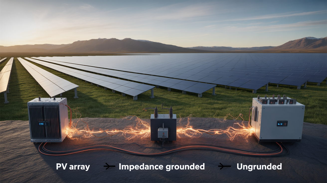
I commonly encounter three AC grounding approaches: solidly grounded, high-impedance grounded, and ungrounded (or effectively ungrounded). The presence/absence of isolation transformers and grounding transformers matters, and I document it up front because it directly shapes both protection pickup logic and overvoltage behavior (EPRI on overvoltages).
IBR fault currents: what I actually see
With synchronous machines I expected large subtransient fault currents. With IBRs, current is power-electronic and control-limited: the response window is tighter and often closer to rated current than legacy protection assumes. Multiple studies describe this software-bounded behavior and the need to coordinate with modern interconnection rules (NREL 2020 DER fault response; IEEE 1547 highlights via NREL; IEEE 1547-2018).
Symmetrical vs asymmetrical faults in practice
Three-phase faults in my tests tend to be handled by inverter current limits and ride-through logic. Single line-to-ground faults reveal the grounding choice: solidly grounded systems produce detectable ground fault currents for overcurrent relays; high-impedance grounded and ungrounded systems yield very small ground currents, shifting the burden to voltage-sensing schemes and sensitive ground detection (EPRI).
How grounding changes the fault picture
I benchmark topologies qualitatively rather than promising a fixed ampere value, because device limits, transformer Z, line length, and inverter control modes move the number. Here’s how I frame trade-offs during design reviews, then I validate with simulations and site tests.
| Characteristic | Solidly Grounded | High-Impedance Grounded | Ungrounded / Effectively Ungrounded |
|---|---|---|---|
| Ground fault current visibility | High: overcurrent elements see it | Low: sensitive ground/voltage elements | Very low: voltage-based detection |
| Transient overvoltage on unfaulted phases | Low (good reference) | Managed (by design) | Can rise significantly; careful control needed |
| Service continuity on first ground fault | Trip preferred for safety | Often alarm and continue to locate fault | Often alarm and continue; monitor closely |
| Typical detection toolbox | OC, GF, directional elements | Neutral voltage/current, sensitive GF | Voltage-based ground detectors |
Why I’m cautious with ungrounded sections: unfaulted phases can float toward line-to-line potential during a ground fault, which I’ve verified with transient captures and which reference material explains conceptually (EPRI).
From standards to settings: how I coordinate protection
Modern interconnection rules require IBRs to stay connected through specified voltage/frequency excursions while supporting the grid. That means my relay and inverter settings must honor ride-through windows and trip curves defined in IEEE 1547-2018 and utility-specific guidance (IEEE 1547 highlights; utility implementation example).
My workflow
- Model the system with realistic inverter current limits and control modes; validate against a commissioning test plan (NREL DER fault response).
- Choose grounding consistent with protection visibility and service needs; document residual-voltage behavior for unfaulted phases (EPRI overvoltages).
- Align relay/inverter settings with IEEE 1547 ride-through and utility tariffs; coordinate the closest device to trip first (IEEE 1547-2018).
How I simulate and verify
Before energization I run fault studies with the inverter models provided by vendors, then I confirm in the field: staged ground-fault tests where allowed, neutral-shift captures, and IR/thermal scans around connection points. Guidance from grid-code literature supports combining verified models with physical testing (IRENA grid codes).
Design notes I keep in my binder
- Solidly grounded: clean detection and simple coordination; watch arc-flash studies and conductor duties—size/clear faster rather than rely on low Z.
- High-impedance grounded: better control of transient overvoltage than legacy ungrounded, with continued operation on first fault—requires sensitive detection and disciplined maintenance.
- Ungrounded/effectively ungrounded: maximizes continuity on first fault but demands vigilant monitoring; unfaulted-phase voltage rise is a known behavior that I document and alarm.
A forward-looking take
As IBR penetration increases, I design from the standard down and from the site up: pick the grounding that makes the fault “visible” to protection, honor ride-through obligations, and verify with data. When those three align, nuisance trips fall and safety margins improve.

Leave a comment
All comments are moderated before being published.
This site is protected by hCaptcha and the hCaptcha Privacy Policy and Terms of Service apply.