In my commissioning and model-audit work, I have learned that the reliability of PV+storage is determined less by brand names and more by how three roles interlock: the energy storage system (ESS), the battery management system (BMS), and the inverter. Below I formalize each role, then introduce quantitative checks and a coordination layer that I use to prevent subtle failure modes.
Clear, testable definitions
ESS — Energy Storage System
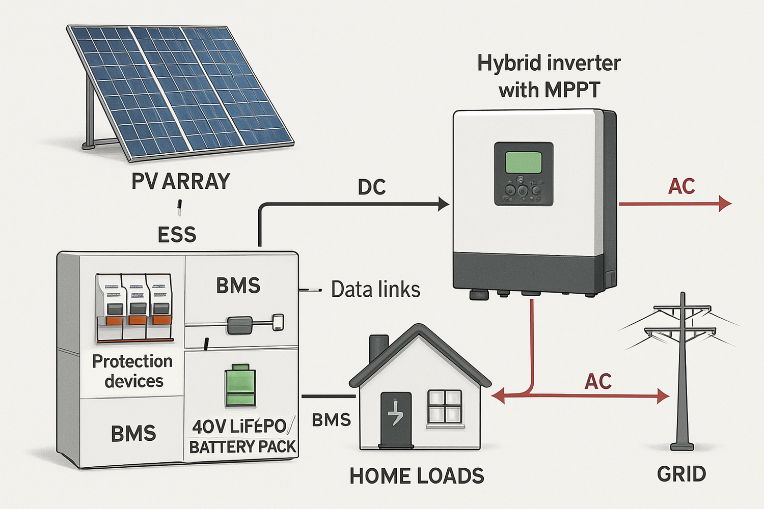
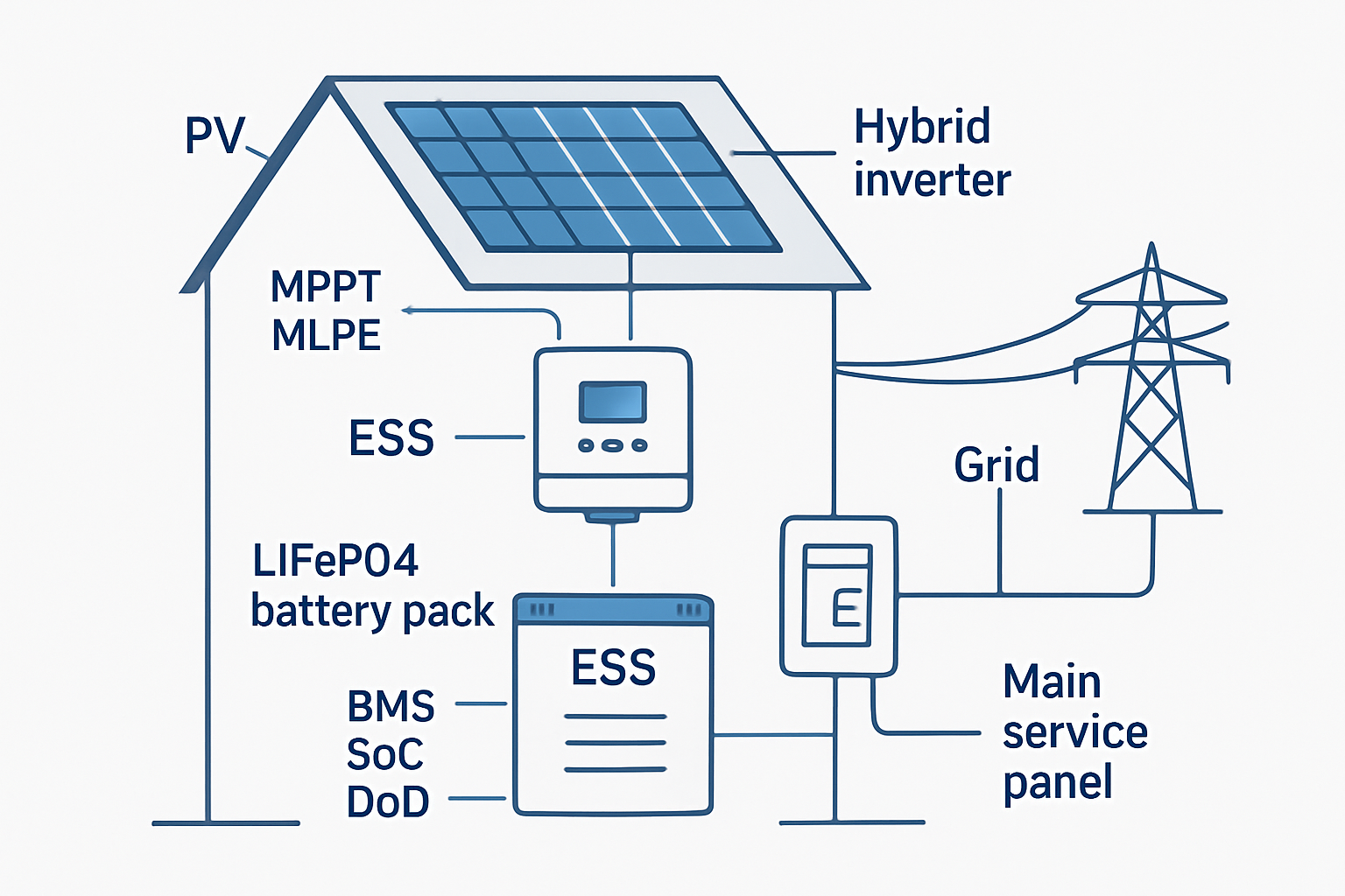
An ESS is the complete storage subsystem: cells/modules, BMS, power electronics, enclosures, contactors, protections, wiring, and controls. In residential projects it is often integrated with a hybrid inverter; in larger sites the ESS interfaces with a site controller. ESS converts variable PV into dispatchable energy and provides ride-through or backup.
For broad system framing, see institutional overviews from the IEA and the U.S. DOE, which place inverters and storage within balance-of-system practice.
BMS — Battery Management System
The BMS enforces safe operating limits and equalizes cells. It measures per-cell voltage and module temperatures, estimates state of charge (SoC) and state of health (SoH), and opens contactors on excursions. For LiFePO₄, a BMS is mandatory; it also communicates export/import current limits to the inverter or site controller.
Inverter
The inverter converts DC to AC and—when hybrid—executes MPPT, battery charge control, and transfer logic for backup. Grid-tied units synchronize to the utility; grid-forming modes can establish voltage and frequency for critical loads. Settings must respect BMS-provided current and temperature limits.
How they coordinate: power, data, and safety
Power path
- DC-coupled: PV strings land on the hybrid inverter’s MPPT; the battery sits on the DC bus—fewer conversion stages and higher round-trip efficiency in self-consumption regimes.
- AC-coupled: A PV inverter feeds AC; a battery inverter charges/discharges on AC—retrofit-friendly and modular for staged expansion.
Data path
The BMS publishes SoC, SoH, Ichg,max, and Idis,max over CAN/RS485. The inverter limits setpoints to remain within those bounds; this prevents nuisance trips and preserves cycle life.
Safety chain
- BMS actions: contactor open on over/under-voltage, over-current, or temperature faults; event logging.
- Inverter actions: anti-islanding, over/under-frequency and voltage ride-through according to interconnection rules.
- Hardware layer: DC fuses/breakers, surge protection, and manual disconnects on battery and PV feeders.
Key specs and realistic ranges (LiFePO₄ home/C&I)
| Component | Core functions | Typical ratings | Practical checks |
|---|---|---|---|
| ESS | Energy shifting; backup | RTE 90–95%; usable DoD 80–90%; 3,000–6,000 cycles @80% DoD; charge 0–45°C; discharge −20–55°C | Usable kWh = nameplate × DoD; disable charge <0°C unless heated |
| BMS | Protection; balancing; telemetry | Cell OV ≈ 3.55–3.65 V; UV ≈ 2.5 V; module continuous ≈ 100 A per ~5 kWh; surge 1.5–2× for 5–10 s | Pack current ≥ inverter DC demand at peak; sensors per module |
| Inverter (hybrid) | DC–AC; MPPT; charge control | 3–10 kW continuous; surge ≈ 2×; MPPT window ~120–500 Vdc; efficiency 95–98%; THD <3% | Cold-string VOC < max input; largest motor start ≤ surge envelope |
Sizing rules that avert hidden bottlenecks
Battery current vs. inverter power
Approximate DC current: I ≈ P / (V × η). For a 48 V pack and η ≈ 0.94, 6 kW requires ≈ 6,000/(48×0.94) ≈ 133 A. If the BMS allows 100 A per 5 kWh module, you need ≥ 2 modules in parallel to sustain 6 kW with headroom.
Surge coordination
Match inverter surge (2–3× for seconds) with BMS surge-current allowance and cable ampacity. A surge-capable inverter is insufficient if the BMS trips first.
Energy balance
- Battery (kWh) ≈ daily load × autonomy (days) ÷ usable DoD.
- PV (kWp) ≈ daily load ÷ peak-sun-hours ÷ system derate (0.75–0.85).
Ensure string counts satisfy coldest VOC and hottest VMP constraints from the inverter manual.
New viewpoints and diagnostic metrics
- Current Headroom Index (CHI): (BMS Idis,max − required DC current at peak load) / required DC current. Keep CHI ≥ 0.25 to avoid thermal drift into trips.
- Trip-Energy Budget (TEB): Maximum allowable I²t over 10 s vs. motor-start demand; require TEB ≥ 1.2× for worst-case starts.
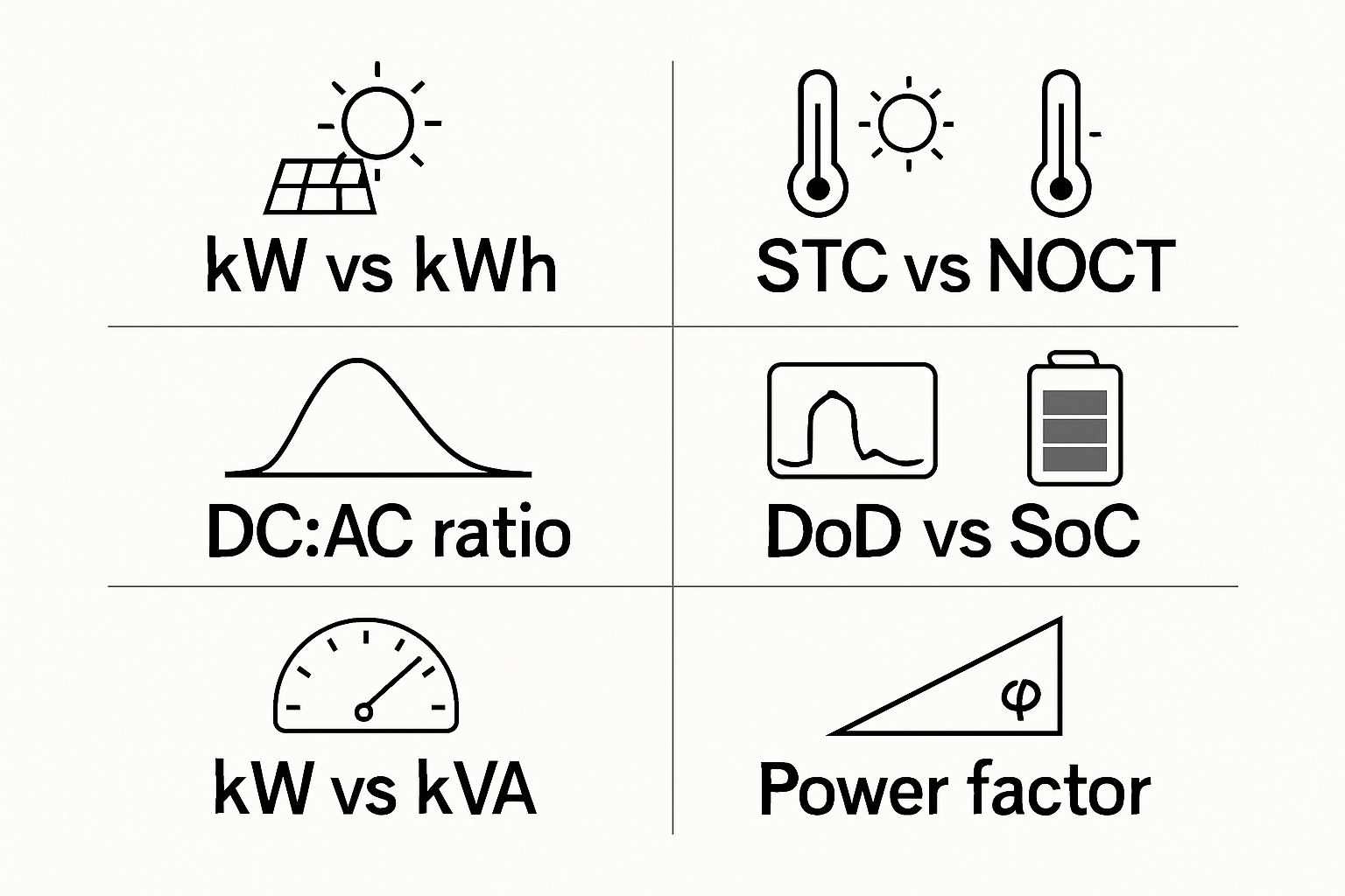
- SoX Matrix: Track SoC (availability), SoH (capacity retention), and SoR (state of resistance) together; rising SoR predicts voltage sag under surge long before capacity fade is obvious.
- Telemetry Contract: Specify update rates and fields (SoC, SoH, Ichg,max, Idis,max, faults). Many field issues trace to stale or missing limits, not bad hardware.
- Coupling Choice by Stage Count: For self-consumption with frequent PV→battery→load paths, DC coupling minimizes conversion stages; for retrofit, AC coupling wins on deployment speed. Quantify by counting conversions in dominant energy paths.
Case snapshot (clinic-scale)
A clinic brief: ~26 kWp PV, 102 kWh LiFePO₄, 35 kVA inverter; peak ~6.4 kW; daily ~35 kWh. Battery-to-load ≈ 3× daily kWh gives overnight autonomy; inverter kVA covers motor starts; PV kWp restores charge within daylight windows. Similar ratios scale to homes and farms.
Installation and operation essentials
Wiring and protection
- Use DC-rated breakers/fuses near batteries and PV inputs; DC arcs persist.
- Keep battery cables short; size for continuous current with 25–40% margin; use busbars for ≥3 parallel strings.
- Bond enclosures; follow local earthing and clearance rules.
Chemistry-aligned settings
- Set charge ceiling per vendor limits; many LiFePO₄ packs favor ≈3.45–3.55 V/cell. Operating at 95–98% SoC often extends life.
- Inhibit charge below 0 °C unless heated; enforce BMS current limits in firmware.
- Calibrate SoC after commissioning if required by the vendor.
Monitoring
- Enable event logs; investigate BMS trips for loose lugs or weak cells.
- Apply scheduled firmware updates; read safety notes.
- Capacity check every 12–24 months for critical sites.
For background on PV systems and BOS, see IEA and DOE. For resource inputs and validation datasets, consult NREL. These sources support the definitions and sizing logic presented here.
Key takeaways
ESS stores energy; the BMS guards its limits; the inverter mediates energy with the grid and loads. Make these elements cohere by specifying data limits, matching surge envelopes, and maintaining current headroom. When those constraints are explicit, PV+storage operates predictably and bankably.
Disclaimer: General technical information only; not legal, code, or design approval. Work with qualified professionals and local standards.


Leave a comment
All comments are moderated before being published.
This site is protected by hCaptcha and the hCaptcha Privacy Policy and Terms of Service apply.