Sizing a solar inverter isn't just about matching numbers; it's a careful balancing act between performance, regulations, and profit. I've spent years designing systems, and I've seen firsthand how a poor sizing choice can lead to failed inspections, crippling power clipping, or even penalties from the utility. This isn't just theory—it's about ensuring your project is compliant and performs as expected from day one.
Forget the dense engineering manuals. I'm going to walk you through my practical, field-tested method for sizing inverters for any project, from a home rooftop to a small commercial array, so you can get it right the first time.

The Three Pillars of Compliant Inverter Sizing
Before we get into numbers, you have to understand the three forces at play. Every decision is a trade-off between them.
1. Inverter Loading Ratio (ILR): The Performance Engine
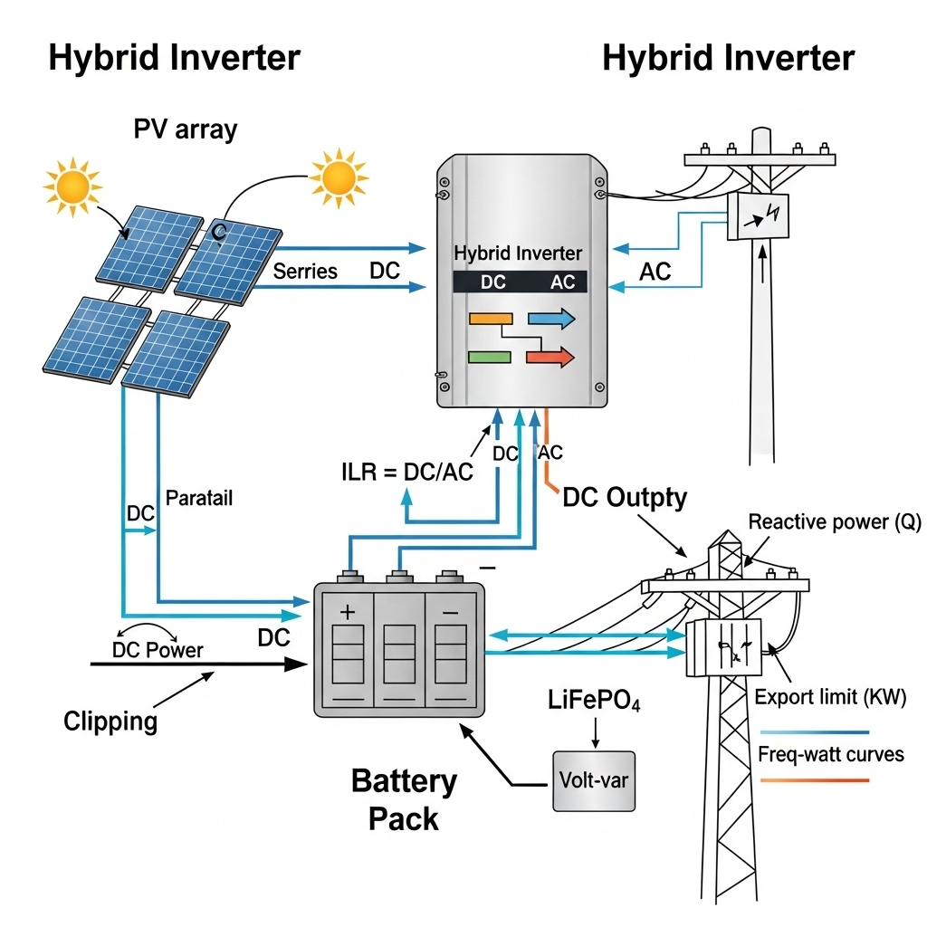
Simply put, **ILR is your solar array's DC power divided by the inverter's AC power rating**. Think of it as how hard you're pushing your inverter. An ILR of 1.0 means a 10 kW solar array is paired with a 10 kW inverter. In reality, we almost always "overload" the inverter with a higher DC input, targeting an ILR between 1.2 and 1.6. Why? Because it boosts energy production on cloudy days and during the morning and evening hours. The trade-off is "clipping"—losing some potential power on perfectly sunny, cool days when the DC array's output exceeds what the inverter can handle.
2. Grid Codes: The Rulebook from Your Utility
The utility doesn't just want your power; they want it delivered in a specific way to keep the grid stable. Grid codes are the rules you must follow. These often demand complex capabilities like voltage support (volt-var), frequency regulation, and limiting how fast you can ramp up power. As more renewables come online, these rules are becoming stricter, as noted in reports like IRENA's global grid code summary.
3. Hybrid Inverters: The Smart Coordinator
A hybrid inverter is a game-changer. It doesn't just convert DC to AC; it manages energy flow between your solar panels, batteries, and the grid. This is crucial for compliance. Instead of just clipping excess DC power, a hybrid inverter can redirect it to charge a battery. This is how you meet strict "export limits" (rules capping how much power you can send to the grid) without wasting a single electron.
My 3-Step Method for Compliant Sizing
Here’s the process I follow to navigate these factors and arrive at a compliant, high-performance design.
Step 1: Define Your AC Power "Box" from the Grid Code
Before you even think about solar panels, start with the utility's interconnection agreement. This document defines the "box" you have to operate within. The most important number is the **export cap (kW)**. If the utility says you can only export 10 kW, that's your starting point. Then, look for power factor requirements. If they require a 0.95 power factor, it means your inverter needs extra capacity (kVA) for voltage support. For a 10 kW export at 0.95 PF, you need an inverter with at least 10.5 kVA (10 / 0.95) to do both jobs at once without overheating or derating.
Step 2: Choose Your ILR Based on Climate and Goals
With your AC inverter size set, now we can determine the DC solar array size. A higher ILR works well in climates that are often cloudy or for customers on time-of-use rates where midday clipped energy is less valuable anyway. In hot, sunny climates, I tend to use a lower ILR to minimize clipping losses. A good simulation tool is your best friend here, but these are solid starting points:
- Residential Rooftop (5 kWac inverter): I'd typically pair this with 6.5 to 8 kWdc of solar panels (ILR 1.3–1.6).
- Commercial Rooftop (100 kWac inverter): I'd aim for 120 to 150 kWdc of panels (ILR 1.2–1.5), as commercial projects are often more sensitive to clipping losses.
Step 3: Program Your Hybrid System for Compliance First
If you have a hybrid system with a battery, the Energy Management System (EMS) is your key to compliance. I always program the controls with a clear priority list:
- Never exceed the AC export limit. This is rule number one.
- If DC power from the panels exceeds the export limit, use the excess to charge the battery.
- Only when the battery is full and you're at your export limit should the system begin to curtail (throttle back) the solar panels.
This strategy maximizes the value of your energy while keeping the utility happy. We’ve seen this work incredibly well in real-world microgrids, as documented in this U.S. DOE success story.
A Real-World Example: A Residential Hybrid System
Let's make this real. A homeowner has a **10 kW export limit** from their utility and wants to maximize their solar usage with a battery.
- AC Inverter Choice: To be safe with power factor requirements, I select an inverter rated for 10 kW of real power and at least 11 kVA of apparent power. This gives us headroom for grid support.
- Solar Array Sizing: We want to maximize production, so we go with a 15 kWdc solar array, giving us an ILR of 1.5. We know it will clip on perfect sunny days.
- Battery & EMS: We add a 10 kWh battery. The EMS is programmed to start charging the battery with any solar power generated above the 10 kW export limit.
The result? The system never sends more than 10 kW to the grid. On a sunny afternoon when the panels are producing 14 kW, 10 kW is exported and the other 4 kW charges the battery for use that evening. No energy is wasted, and the system is 100% compliant.
My Final Pro-Tips for Sizing
- Always Reserve Headroom: Never size your inverter's kVA exactly to the export cap if reactive power support is required. That 5-10% buffer is your compliance insurance.
- Model, Don't Guess: Use software to simulate your annual clipping losses. A 2% loss might be acceptable; a 10% loss probably means your ILR is too aggressive for your climate.
- Check the Certificates: Ensure your chosen inverter is certified for the specific grid code requirements in your area (e.g., voltage ride-through). Don't just take the datasheet at face value.
By starting with the utility's rules and working backward, you can design a system that not only passes inspection but also delivers on its promise of clean, reliable energy for years to come.


Leave a comment
All comments are moderated before being published.
This site is protected by hCaptcha and the hCaptcha Privacy Policy and Terms of Service apply.