
Right-size the inverter and your PV system runs cooler, lasts longer, and delivers higher energy. Miss the details and you pay in clipping losses, nuisance trips, and premature failures. This piece pinpoints seven common inverter sizing mistakes, why they hurt inverter lifetime and PV system yield, and how to fix them with practical rules, backed by research and grid-code guidance.

Context that matters
Inverters are more than DC-to-AC boxes. They provide grid support, must ride through disturbances, and operate safely within harmonic limits. Research notes the limited overcurrent capacity of PV inverters and reduced fault currents in systems with high inverter-based resources, which complicates protection and coordination. These realities affect sizing decisions and required headroom (IRENA grid-code brief).
Grid-following inverters also keep adding features for reliability services, not just conversion, which changes the way we allocate reactive power and thermal margins (U.S. DOE Solar Energy Technologies Office). Energy statistics and capacity factor baselines are available for planning and validation (IEA; EIA).
Mistake 1: Ignoring thermal and altitude derating
Most inverters reduce output as internal temperatures rise. High ambient temperature, direct sun on the enclosure, and limited airflow accelerate heat stress. At higher elevations, thinner air reduces convective cooling, compounding derating.
- Symptoms: Power roll-off in the afternoon, frequent thermal alarms, shorter component life (capacitors and semiconductors).
- Impact: Lower daily energy and higher lifetime stress; accelerated capacitor aging per 10°C temperature rise can be significant.
- Fix: Size the inverter using local design temperatures, not averages. Add shade, airflow, or a higher AC rating. For rooftops, avoid south-facing walls and ensure clearance on all sides.
Quick rule
Design for peak-cell temperature days. Combine module temperature coefficients with inverter thermal curves. Reserve at least 10–15% AC headroom in hot climates to reduce thermal clipping.
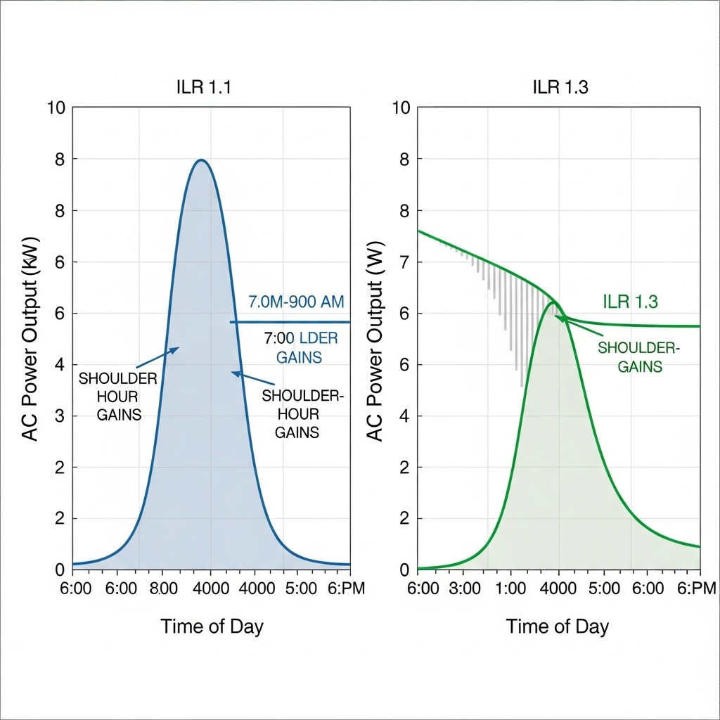
Mistake 2: Oversizing the DC array without quantifying clipping
Inverter loading ratio (ILR = DC array STC power / inverter AC rating) improves energy harvest at low irradiance. Push ILR too high and you clip mid-day power, heat the inverter harder, and risk lower lifetime.
- Symptoms: Flat-topped AC output on clear days, warm enclosure, rising failure rate of fans and capacitors.
- Impact: Energy lost to clipping and extra thermal cycles. In sites with frequent high-irradiance conditions, yield plateau arrives early.
- Fix: Simulate clipping hours and thermal limits, not just annual kWh. Consider climate, tilt, albedo, and bifacial gain. Keep ILR aligned with cooling design and required reactive-power headroom.
Illustrative ILR impact table
| Climate | Example ILR | Approx. annual clipping | Notes |
|---|---|---|---|
| Hot desert, 45°C design ambient | 1.5 | 3–6% | Thermal derating and long high-irradiance windows increase clipping risk |
| Temperate, 30°C design ambient | 1.35 | 1–3% | Balanced yield vs AC limits |
| Cool coastal, frequent clouds | 1.6 | 0.5–2% | Extra DC pays off at low irradiance; limited peak periods |
These are planning ranges from field experience; site-specific modeling is required. For DC-side performance and storage interactions that influence ILR choices, see this reference on practical performance factors (Anern: Solar & Storage Performance Reference).
Mistake 3: Forgetting reactive power and grid-support headroom
Inverters must meet grid codes for voltage regulation, power factor, and often ride-through performance. Running 100% at unity PF leaves no margin for reactive power (Q) support during voltage dips.
- Symptoms: Voltage ride-through failures, curtailment by the utility, and alarms during feeder disturbances.
- Impact: Availability loss and compliance risk. Operating at high Q can raise current and heat, stressing hardware.
- Fix: Reserve apparent power margin. A common practice is to size AC capacity so the inverter can deliver required reactive power while meeting real-power targets. Check local interconnection rules.
Guidance across regions points to harmonic and voltage behavior as compliance metrics. Interharmonics and THD from power electronics can trigger flicker and instabilities; limits are framed in IEEE-519 and IEEE 1547. The IRENA grid-code brief summarizes how these criteria appear in practice.
Mistake 4: Skipping overload and surge needs
Motors, well pumps, heat pumps, and some electronics demand short surges. Storage inverters must also coordinate battery C-rate limits with inverter overload capability.
- Symptoms: Inverter trips on start-up surges, dimming, or frequent current limit warnings.
- Impact: Nuisance shutdowns, reduced perceived reliability, and stress on semiconductor dies.
- Fix: Validate the continuous rating and the overload profile (e.g., 1.2–1.5× for 10 seconds) against site loads. Match battery C-rate and BMS limits to the inverter’s surge and continuous current. The Anern performance reference walks through how inverter limit, battery C-rate, and round-trip losses shape usable energy.
Case tip
For off-grid cabins and farms, add a soft-starter on large motors or choose an inverter with documented surge headroom. If frequent surges coincide with peak PV, ensure thermal margin to avoid simultaneous overload and heat stress.
Mistake 5: Overlooking low-irradiance efficiency and mismatch
Some inverters excel at full load yet fall off at dawn, dusk, or in cloudy conditions. Mismatch and partial shading can further reduce harvest if string current is set by the weakest module.
- Symptoms: Underperformance in shoulder hours, high mismatch losses in shaded rows.
- Impact: Lower capacity factor and reduced return on the DC investment.
- Fix: Compare efficiency curves at 5–20% of rated power. Consider module-level power electronics or parallel wiring topologies to allow each module to operate independently. A DOE EERE success story shows how a converter enabling parallel wiring increased output by letting modules run at their own operating point while maintaining high DC voltage to the inverter.
Mistake 6: Missing harmonic limits and filter impacts
Harmonic current limits shape how you size and cool the inverter. If THD must be low at the point of interconnection, your LCL filters and switching patterns raise thermal load and sometimes require apparent power headroom.
- Symptoms: Interconnection test failures, flicker complaints, unexpected heating in filters.
- Impact: Delays in permission to operate, higher losses from filtering, and extra thermal stress.
- Fix: Account for filter losses in sizing and thermal models. Budget current margin for low power factor and harmonic content. Grid-code briefs recommend assessing interharmonics and THD during design (IRENA grid-code brief). IEEE-519 and IEEE 1547 frame current and voltage distortion guidance many utilities reference.
Mistake 7: Neglecting protection, fault current, and ride-through
High shares of inverter-based resources lead to reduced fault currents and bidirectional flows in distribution networks. Legacy protection relying on fault current magnitude and direction may not act correctly if inverters are sized without headroom or proper control features.
- Symptoms: Miscoordination events, false trips, and protection setting disputes.
- Impact: Downtime and added engineering time; potential equipment stress during disturbances.
- Fix: Coordinate with the utility on protection studies. Provide headroom so the inverter can support grid services and primary frequency response when required. Research notes the limited overcurrent capacity of PV inverters and the need for visibility and controllability of DERs; evolving grid-following inverters add capabilities beyond conversion (IRENA grid-code brief; DOE SETO).
Worked sizing example
Goal: 100 kWdc PV on a hot site (45°C design ambient), LiFePO4 storage, mixed daytime loads.
- Base: 100 kWdc array, module temperature coefficient around −0.35%/°C.
- Candidate inverter: 75 kWac, full power to 40°C, linear derating to 0.9 p.u. at 50°C internal temp.
- Estimated ILR: 1.33. Modeled clipping: about 1–3% annually in a temperate site, higher under heat.
- Thermal risk: Afternoon internal temps can exceed 50°C; expect derating at the same time as clipping.
- Adjustment: Move to 80–90 kWac or add shade and forced ventilation. Keep 10% apparent power headroom for Q support and filtering.
- Storage: Battery continuous C-rate must support inverter’s AC output. For a 90 kWac inverter at 400 Vdc, DC current must align with BMS limits. The Anern reference outlines how inverter ceiling, battery discharge rates, and temperature impact usable energy and round-trip efficiency.
Quick comparison
| Option | AC size | Expected clipping | Thermal margin | Pros | Cons |
|---|---|---|---|---|---|
| A | 75 kWac | 2–5% | Low | Lower upfront cost | Higher afternoon derating risk; less Q headroom |
| B | 85 kWac | 1–3% | Medium | Balanced yield; better grid support | Slightly higher CapEx |
| C | 100 kWac | ≈0–1% | High | Max real-power headroom; ample Q | Higher CapEx; may underutilize AC in cool seasons |
Pick the option that meets your thermal and compliance envelope at the lowest lifecycle cost. Use local weather files and inverter datasheets to refine these ranges. For baseline energy statistics and validation, see IEA and EIA resources.
Practical sizing checklist
- Set ILR by climate and tilt; quantify clipping hours, not just annual kWh.
- Thermal plan: Mount in shade, ensure airflow, and model altitude impacts.
- Grid support: Reserve apparent power for power factor and ride-through.
- Harmonics: Include filter losses and THD limits in your current and heat budget.
- Overload: Match surge profile to loads; align battery C-rate with inverter limits.
- Low-light performance: Compare efficiency curves at 5–20% load; address mismatch.
- Protection: Coordinate with the utility for DER visibility and settings; verify bidirectional current effects.
Why this protects lifetime
Every degree of internal temperature and every ampere above nominal affects semiconductor junctions and electrolytic capacitors. Reducing thermal stress, avoiding constant clipping, and keeping harmonic current within limits extend inverter lifetime and stabilize yield. This aligns with the broader shift toward inverters that support reliability services, as noted by DOE SETO, and with grid-code expectations summarized by IRENA. Module-side strategies to reduce mismatch and enhance low-light energy, such as parallel wiring with DC voltage boosting, also raise yield as highlighted by the EERE success story.
Key takeaways
- Size for heat and headroom first; then optimize ILR.
- Reserve apparent power for reactive support and harmonic compliance.
- Validate overload needs and storage C-rate limits together with inverter ratings.
- Use independent module operation or careful stringing to cut mismatch losses.
- Coordinate protection and ride-through early to prevent costly changes later.
Authoritative context and statistics: IEA, EIA, DOE SETO, and IRENA grid-code brief. Engineering choices should be validated with site-specific studies and inverter datasheets.
Disclaimer: Technical guidance only. Site engineering, local codes, and utility requirements prevail. This is not legal advice.
FAQ
What ILR should I target if I need both yield and lifetime?
In temperate sites, many designers sit near 1.25–1.35 to balance low-light gains with manageable clipping and heat. In hot sites, reduce ILR or add AC headroom. Always simulate clipping hours and internal temperature, not just annual kWh.
How much apparent power headroom do I leave for reactive power?
A practical starting point is 5–15% depending on local interconnection rules and voltage-control needs. Confirm with the utility and consider harmonic filter losses in the same margin.
Do batteries change inverter sizing?
Yes. The inverter’s continuous and surge current must align with battery C-rate and BMS limits. Improper pairing can limit usable power and raise heat. See the Anern performance reference for interactions that affect delivered energy.
How do I handle hot rooftops?
Use shaded mounts, light-colored backdrops, and adequate spacing for airflow. Consider a higher AC rating or forced ventilation. Model both thermal derating and DC-side temperature effects.
Why do harmonics affect inverter lifetime?
Meeting strict THD and interharmonic limits can increase filter and switching losses, adding heat. Plan for this in your current and thermal margins and verify against IEEE-519/1547 expectations summarized by IRENA.
Leave a comment
All comments are moderated before being published.
This site is protected by hCaptcha and the hCaptcha Privacy Policy and Terms of Service apply.