Right-sizing a solar inverter aligns the DC array and the AC conversion stage so the system runs in its most efficient operating band for more hours. You cut conversion losses, keep thermal stress in check, and reserve kVA for grid support. This piece gives a practical sizing method with numeric ranges, tables, and a worked example for both PV-only and hybrid systems.
Several energy agencies confirm the value of careful sizing. According to System Integration of Renewables, connection assets sized to absolute peak can sit underused most of the day; modest inverter downsizing improves use of the interconnection. The same report shows DC/AC ratios at utility scale have risen in the United States over recent years. IRENA and U.S. DOE Solar Energy highlight the growing role of storage and flexible operation, which also affects the optimal DC/AC choice. The EIA tracks rapid distributed PV growth, reinforcing the need for sizing that supports both yield and grid friendliness.

Right-sizing: what it targets and why it lifts peak efficiency
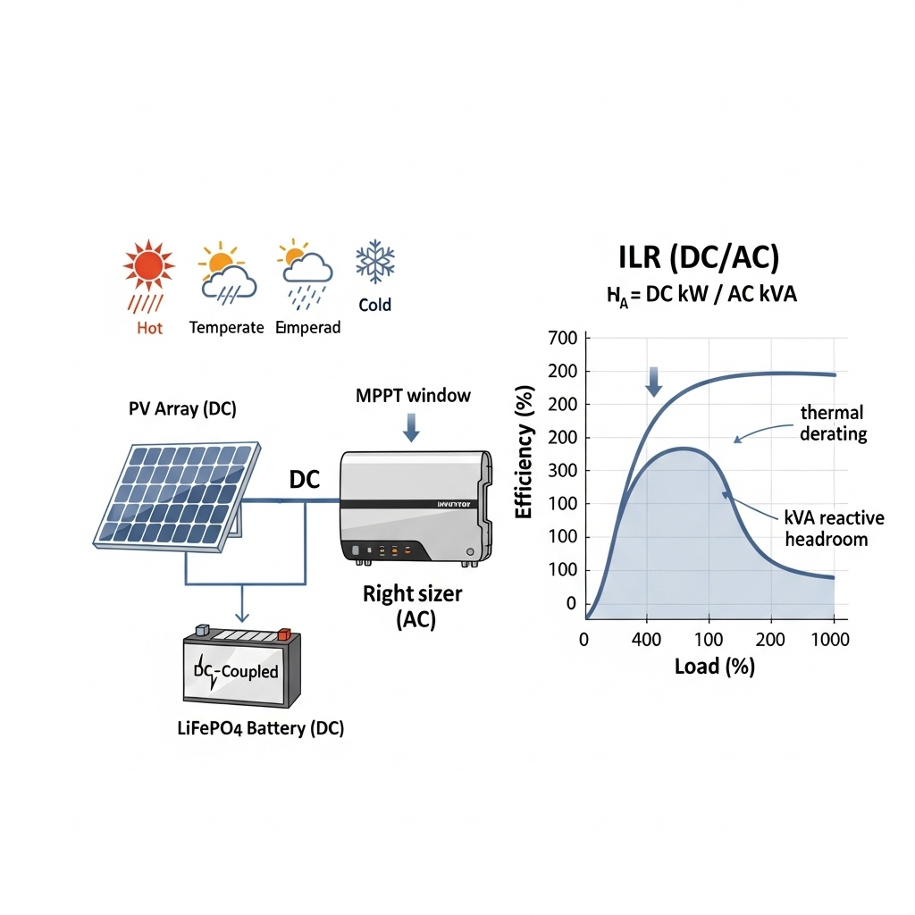
Inverter Loading Ratio (ILR) is the ratio of array DC nameplate to inverter AC rating: ILR = Pdc_stc / Pac_rated. A higher ILR pushes more hours near mid-load on the AC side, where conversion efficiency is usually highest. Most modern string inverters reach their peak efficiency near 40%–80% of rated output. At very low load, auxiliary consumption and switching losses dominate; at absolute full load, thermal limits and switching dynamics may trim efficiency.
According to System Integration of Renewables, sizing connection infrastructure to meet absolute peak DC production leaves capacity unused outside that brief window. Inverter downsizing lifts utilization and can reduce balance-of-plant overspecification. Getting Wind and Solar onto the Grid also stresses that correct technology choices must fit climate and quality standards, which includes thermal derating behavior and MPPT voltage windows.
A step-by-step method to size for efficiency gains
1) Gather site and equipment inputs
- Weather and irradiance: annual GHI/DNI, temperature min/max, typical heatwaves.
- Module data: Voc, Vmp, temperature coefficients, string length options.
- Inverter data: max DC input, MPPT voltage range, max DC short-circuit, kVA rating, partial-load efficiency curve, thermal derating curve, reactive power capability.
- Grid requirements: required power factor range, voltage-ride-through, any kVA headroom rules.
- Storage plan: DC-coupled or AC-coupled, desired charge windows, round-trip efficiency.
2) Check DC voltage and current limits
- At minimum site temperature, ensure string Voc stays under inverter max DC voltage with margin (commonly 5%–10%).
- At maximum site temperature, ensure Vmp stays inside the MPPT window for typical operating hours.
- Check combined Isc vs inverter input current limit and per-MPPT allocation.
3) Choose a target ILR by climate and use case
These ranges aim to keep the inverter inside its high-efficiency band for more hours, while managing clipping risk and thermal limits. They also account for the gain from morning and afternoon energy.
| Segment | Climate | Storage | Recommended ILR | Notes |
|---|---|---|---|---|
| Residential rooftop | Hot | No | 1.15–1.25 | Higher temps push thermal derating; keep ILR modest. |
| Residential rooftop | Temperate | No | 1.20–1.35 | Good balance of partial-load efficiency and limited clipping. |
| Residential rooftop | Cold | No | 1.25–1.40 | Cold air boosts array output; watch voltage at Tmin. |
| Commercial | Hot | No | 1.15–1.30 | Roof heat islands increase inverter temps. |
| Commercial | Temperate/Cold | No | 1.25–1.45 | Roof ventilation and shade plan matter. |
| All segments | Any | DC-coupled battery | +0.05–0.15 over PV-only | Storage can absorb peaks and shift energy, easing clipping and lifting efficiency hours. |
Context: U.S. utility systems have trended toward higher DC/AC ratios over time as documented by the IEA analysis of industry data (System Integration of Renewables).
4) Reserve kVA for reactive power
If the site must maintain 0.95 power factor at full active power, select an inverter with sufficient apparent power so active power setpoints do not hit a ceiling while providing vars. A common rule is to keep 5%–10% kVA headroom for reactive support during high-voltage or low-voltage events. This aligns with grid code guidance and good practice in DOE solar topics.
5) Thermal derating and airflow
High ambient temperatures and poor airflow can trigger derating. Use inverter thermal curves and local Tmax data. In hot sites, either increase heat dissipation (shade, spacing, heatsinks, forced ventilation) or reduce ILR by 0.05–0.1. IEA emphasizes that equipment should suit humidity and temperature conditions; that applies directly to inverter heatsinks and enclosure ratings.
Partial-load curves: where real efficiency gains appear
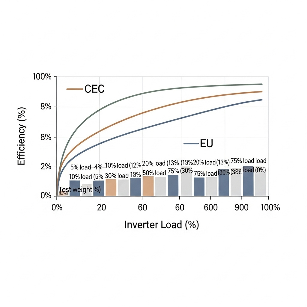
Inverter conversion efficiency is not flat across load. A typical high-quality unit shows values in the range below (illustrative; check your datasheet):
| AC Load (% of rated) | Typical Conversion Efficiency | Notes |
|---|---|---|
| 10% | 92%–95% | Auxiliary power dominates, switching losses proportionally higher. |
| 50% | 97.0%–98.2% | Near peak point on many CEC- or EU-weighted curves. |
| 75% | 97.5%–98.5% | Often the absolute peak. |
| 100% | 96.5%–98.0% | Thermal and switching limits flatten or dip the curve. |
Target ILR so that the typical operating band sits inside 40%–80% for as many hours as possible. This increases daily AC yield with the same irradiance. It also reduces time spent at very low AC output where fixed losses erode performance.
Storage can help hold operation near this sweet spot. As summarized in Ultimate Reference: Solar & Storage Performance, LiFePO4 systems deliver high round-trip efficiency and cycle life that depends on depth of discharge. Charging during strong sun and discharging during shoulder hours can keep the inverter near its high-efficiency region while reducing grid imports. Numbers vary by product; always verify with the battery and inverter datasheets.
Worked sizing example: 12.5 kWdc array, two AC options
Site: temperate climate, rooftop, good airflow. Modules yield 12.5 kWdc STC. Two inverter choices:
- Option A: 10 kWac inverter (ILR = 1.25)
- Option B: 8 kWac inverter (ILR = 1.56)
Assumptions: inverter partial-load curve peaks at 98.2% near 70% load; 97.0% at 50% load; 96.7% at 100% load. Annual irradiance profile yields a midday DC peak near STC on rare clear, cool days, more often 80%–90% of STC.
- Option A: Operating band clusters around 50%–90% of rated AC for more hours. Occasional clipping on rare, cool, cloudless days. Weighted conversion may average ~97.6% across the year.
- Option B: Operating band often near 60%–100% of rated AC with frequent mid-summer clipping. Weighted conversion near ~97.9%, but clipping may trim net AC yield depending on climate and tilt.
Net result: In temperate sites, ILR ~1.2–1.35 usually balances conversion gains and low clipping. In very hot sites, extra thermal headroom favors the 10 kWac choice at ILR ~1.2–1.25. If a DC-coupled battery is present, the 8 kWac option can still perform well, because storage will absorb some peaks and shift output. These trade-offs align with IEA guidance that moderate downsizing improves interconnection use (link).
Hybrid systems: right-size with LiFePO4 storage
Pairing PV with LiFePO4 storage changes the sizing calculus:
- DC-coupled storage reduces double-conversion losses and can absorb brief peaks, supporting a slightly higher ILR while keeping clipping in check.
- Round-trip efficiency and depth-of-discharge strategy affect daily economics. The resource Ultimate Reference: Solar & Storage Performance outlines typical performance patterns and operating advice that you can align with your EMS settings.
- Schedule charging during the high-irradiance window to keep the inverter between 50%–80% of rating. Schedule discharge across evening peaks to reduce imports and support local loads.
Be sure to validate battery charge current limits per MPPT, DC bus voltage coordination, and anti-backfeed rules. DOE solar resources and IRENA offer high-level frameworks for PV-plus-storage planning that you can adapt to local codes.
Procurement and standards: avoid hidden losses
Quality and suitability to local conditions matter as much as nameplate ratings. As noted in Getting Wind and Solar onto the Grid, equipment should match humidity, temperature, and other site conditions. That applies to conformal coating, enclosure rating (NEMA/IP), salt-mist resistance, and thermal design. Early-stage projects benefit from proven models with documented partial-load curves and independent test data.
- Request CEC- or EU-weighted efficiency plus a granular partial-load curve.
- Check MPPT current per tracker against expected string currents in cold clear conditions.
- Verify reactive power capability and communication protocols for grid support modes.
- Confirm warranty language on DC oversizing and clipping; stay within allowed ILR.
Quick calculator and comparison
| Parameter | Case 1 | Case 2 |
|---|---|---|
| Array DC (STC) | 12.5 kW | 12.5 kW |
| Inverter AC | 10 kW | 9 kW |
| ILR | 1.25 | 1.39 |
| Weighted inverter efficiency | ~97.6% | ~97.8% |
| Estimated annual clipping | ~0.5%–1.0% | ~1%–2% |
| kVA headroom at PF 0.98 | 2%–4% | 2%–4% |
| Suitability | Hot to temperate sites | Temperate to cold or DC-coupled storage |
These figures are indicative; confirm with local weather files and the exact inverter curve. Use a year-of-data simulation for final selection. IEA and EIA resources can help set context for local load shapes and policy requirements.
Actionable sizing checklist
- Define ILR target from the table above based on climate and storage plan.
- Validate MPPT voltage range at Tmin/Tmax; keep 5%–10% safety margin.
- Reserve 5%–10% kVA for reactive support if required.
- Review thermal curve vs site Tmax; apply shading and spacing if needed.
- For hybrids, tune EMS so PV charging holds the inverter near 50%–80% of rating during high-irradiance hours.
- Document warranty limits on DC oversizing.
According to DOE solar topics, storage and flexible operation will expand across the grid. That trend increases the value of inverters sized not only for energy yield but also for grid services. IRENA guidance on renewables integration points in the same direction.
Technical disclaimer: Numbers and ranges in this piece are indicative only and do not replace stamped engineering. Verify with local codes, utility rules, and equipment datasheets.
FAQs
What ILR should I aim for on a small rooftop system?
For temperate rooftops without storage, an ILR of 1.20–1.35 usually keeps the inverter in a high-efficiency band for more hours with limited clipping. In hot climates, start near 1.15–1.25 due to thermal derating risk. Always confirm with local weather files.
Does a larger inverter always reduce yield loss?
Not always. A larger AC rating lowers clipping but can push many hours into low load where efficiency dips. A moderate ILR often increases net AC energy because more hours sit in the 40%–80% high-efficiency region. Balance both effects with a year-long simulation.
How does temperature affect the choice?
High ambient temperature accelerates thermal derating and raises auxiliary fan use. Either lower ILR slightly or improve ventilation and shading. In cold sites, watch string Voc at Tmin and keep a safety margin under the inverter max DC voltage.
How do I size a hybrid inverter with a LiFePO4 battery?
Coordinate DC bus voltage, MPPT current limits, and battery charge current. A DC-coupled battery can justify a slightly higher ILR because it absorbs brief peaks and shifts energy. Use operating advice such as that summarized in Ultimate Reference: Solar & Storage Performance to set EMS charge and discharge windows.
Is DC oversizing safe for warranties and grid codes?
Many inverters allow DC oversizing within stated limits. Check datasheets and warranty terms. Grid codes may also require power factor or voltage ride-through, which can affect kVA sizing. Refer to IEA quality guidance and local regulations. This is not legal advice.


Leave a comment
All comments are moderated before being published.
This site is protected by hCaptcha and the hCaptcha Privacy Policy and Terms of Service apply.