As power systems transition towards higher shares of renewable energy, the role of inverters has evolved from simple power converters to active grid stabilizers. A core aspect of this evolution is the inverter's ability to manage voltage at the Point of Common Coupling (PCC), the interface where a solar or storage system connects to the grid. This capability is defined by the dynamic relationship between reactive power (Q), voltage (U), and active power (P), often referred to as the Q-U-P capability.
Understanding the Core Components: Q, U, and P
To appreciate the significance of Q-U-P capability, it's important to understand each component's role in maintaining a healthy and stable electrical grid.
Active Power (P): The Foundation of Energy Delivery
Active power, measured in watts (W) or kilowatts (kW), is the energy that performs useful work. It's the power that runs appliances, charges devices, and drives machinery. In a solar energy system, the inverter's primary job is to convert the DC electricity from solar panels or batteries into usable AC active power that can be consumed on-site or exported to the grid.
Reactive Power (Q): The Key to Voltage Stability
Reactive power, measured in volt-amperes reactive (VAR), does not perform direct work but is essential for maintaining the voltage levels required for active power to flow. It supports the magnetic fields in motors and transformers. Modern inverters can be controlled to either generate or absorb reactive power, which directly influences the voltage at the PCC. Injecting reactive power tends to raise the voltage, while absorbing it tends to lower the voltage.
Voltage (U): The Grid's Pressure Gauge
Voltage (U) at the PCC can be thought of as the electrical pressure in the system. Maintaining this pressure within a specific range is critical for the safe and efficient operation of all connected equipment. Deviations, whether sags or swells, can disrupt operations and even damage sensitive electronics. The increasing penetration of variable renewable energy sources makes active voltage management more important than ever.
The Q-U-P Capability Curve: Visualizing Inverter Performance
The relationship between active power, reactive power, and voltage is not static. It is a dynamic capability that can be visualized through performance maps and curves, defining the operational limits of an inverter under various grid conditions.
What is the Q-U-P Relationship?
An inverter's ability to supply reactive power (Q) is directly dependent on the grid voltage (U) at the PCC and its current active power (P) output. This is the essence of the Q-U-P relationship. Unlike traditional synchronous generators, which often operate near rated power, variable renewable energy (VRE) plants frequently run at partial load. According to a report from IRENA, this makes the reactive power capability of VRE plants a more complex and significant factor in day-to-day operations. The report, Grid Codes for Renewable Powered Systems, emphasizes that how this capability is used affects system currents and losses.

Interpreting the Capability Diagram
The P-Q capability diagram illustrates an inverter's operational boundaries. The outer edge of the curve represents the maximum apparent power (kVA) the inverter can handle. Any combination of P and Q within this boundary is a valid operating point. The diagram shows that as an inverter produces more active power (moving right on the horizontal axis), its ability to provide reactive power (moving up or down on the vertical axis) decreases. Furthermore, the grid voltage (U) can alter the shape of this boundary, affecting the inverter's reactive power range.
Practical Implications for System Design
Engineers must consider the Q-U-P capability to ensure compliance with local grid codes, which are technical rules for grid access. These codes increasingly require solar and storage systems to provide voltage support. To meet stringent reactive power requirements, especially at full active power output, it may be necessary to use an inverter with a higher kVA rating than the kW rating of the solar array. This ensures sufficient capacity is available for both active power delivery and grid support services.
Grid Codes and the Mandate for Advanced Inverter Functions
The evolution of grid codes reflects the shift in how power systems operate. Inverters are no longer passive participants but are required to actively contribute to grid stability through a suite of advanced functions.
From Grid-Following to Grid-Forming
Traditionally, most inverters have been 'grid-following,' meaning they synchronize to an existing grid voltage and act as a current source. However, as the number of traditional rotating generators declines, there is a growing need for 'grid-forming' inverters. These advanced inverters can create their own voltage and frequency reference, allowing them to operate independently and provide a stable backbone for the grid, especially in areas with high renewable penetration or in microgrid applications.
Key Grid Support Functions Enabled by Q-U-P
The Q-U-P capability is the foundation for several critical grid support functions mandated by modern standards like IEEE 1547-2018. These include:
- Volt-VAR Control: The inverter automatically adjusts its reactive power output in response to local voltage changes. If the voltage is too high, it absorbs reactive power; if it's too low, it injects reactive power.
- Volt-Watt Control: If the grid voltage rises above a certain threshold, the inverter will curtail its active power output to help reduce the voltage.
- Fault Ride-Through (FRT): During a grid fault that causes a voltage dip, the inverter must remain connected and support the grid by injecting reactive current to help the voltage recover quickly.
The Evolving Landscape of Grid Codes
Grid codes are continuously updated to address the challenges and opportunities presented by new technologies. According to the International Energy Agency (IEA), smart inverter technology is a key enabler of voltage management and other power system support services. This ongoing evolution requires system designers and engineers to stay informed about the latest interconnection requirements in their jurisdiction.
Optimizing System Performance and Reliability
Leveraging an inverter's Q-U-P capability effectively requires a holistic approach, considering everything from internal components to overall system integration.
The Role of Switching Devices
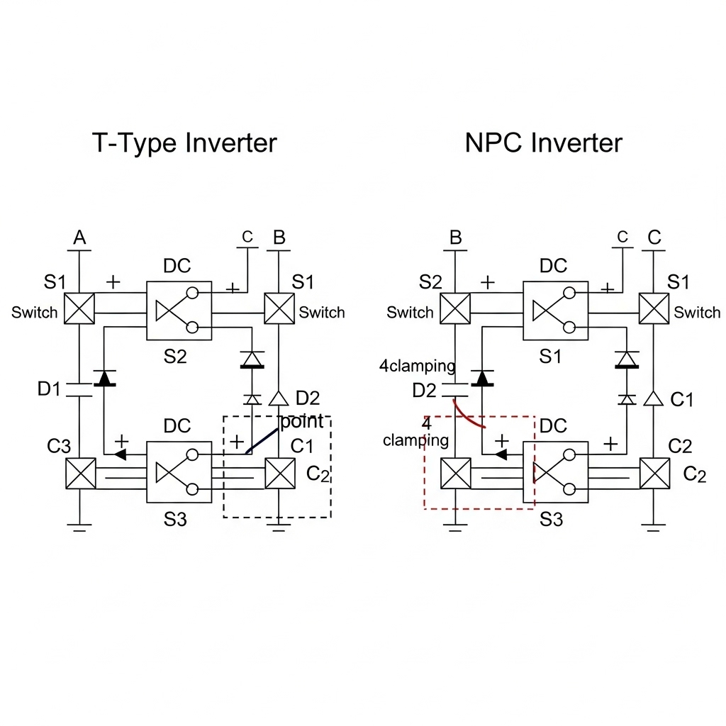
The performance of an inverter, including its efficiency and speed in executing advanced grid functions, is heavily influenced by its internal components. The choice of semiconductor switching devices, such as Silicon Carbide (SiC) or Insulated-Gate Bipolar Transistors (IGBT), plays a crucial role in the inverter's topology and its ability to respond rapidly to grid commands, enabling precise control over active and reactive power.
Balancing Performance and Cost
Providing a wide range of reactive power support comes with trade-offs. A larger Q-U-P capability envelope often requires a more robust, and therefore more expensive, inverter. The operational expenses can also be impacted, as providing reactive power increases the current flowing through the system's components, leading to higher thermal losses in the inverter, cables, and transformers.
The Importance of System-Level Integration
Achieving optimal voltage support is not solely dependent on the inverter. It requires careful consideration of the entire system design. A comprehensive understanding of how components interact is crucial. For instance, evaluating overall solar storage performance involves looking beyond a single component's datasheet and considering the synergy between batteries, inverters, and solar panels, as detailed in this ultimate reference on solar storage performance.
A Forward Look at Inverter-Based Grid Support
The Q-U-P capability is a fundamental characteristic that transforms modern inverters from passive energy producers into active, supportive grid assets. This functionality is no longer a niche feature but a cornerstone of reliable grid operation in an era dominated by renewable energy. As systems move towards being supplied by 100% converter-based sources, the role of advanced inverter topologies, particularly grid-forming capabilities, will become even more critical. Understanding and leveraging the dynamic interplay of reactive power, voltage, and active power is essential for engineers, developers, and operators building the resilient and sustainable energy infrastructure of the future.
Frequently Asked Questions
What is the primary purpose of Q-U-P capability?
Its main purpose is to define an inverter's ability to manage reactive power (Q) based on grid voltage (U) and its active power (P) output. This dynamic control is essential for maintaining grid voltage stability, especially in power systems with high levels of solar and wind generation.
How does Q-U-P differ from a simple power factor rating?
A power factor rating is typically a single, static value that describes the ratio of active power to apparent power under specific conditions. In contrast, Q-U-P capability is a dynamic envelope. It provides a complete picture of an inverter's reactive power support across its full range of active power output and under varying grid voltage conditions, reflecting its true grid support functionality.
Are all solar inverters required to have these advanced capabilities?
Requirements vary significantly based on regional and utility-specific grid codes. However, there is a clear trend globally towards mandating advanced inverter functions like Volt-VAR and fault ride-through. As per reports from organizations like IRENA, these capabilities are becoming standard for new, larger-scale systems connecting to the grid to ensure overall system reliability.


Leave a comment
All comments are moderated before being published.
This site is protected by hCaptcha and the hCaptcha Privacy Policy and Terms of Service apply.