Understanding a solar and lithium battery storage system diagram is fundamental to grasping how your energy independence is achieved. This schematic serves as the blueprint for your entire power system, detailing every component and connection. It is an invaluable tool for installation, maintenance, and troubleshooting. Familiarity with this diagram empowers you to make informed decisions and manage your energy resources effectively.
Decoding the Key Components on the Diagram
Every solar energy storage system diagram illustrates a few core components working in harmony. Recognizing these symbols and their functions is the first step to literacy in solar schematics.
Solar Panels (PV Array): The Power Generators
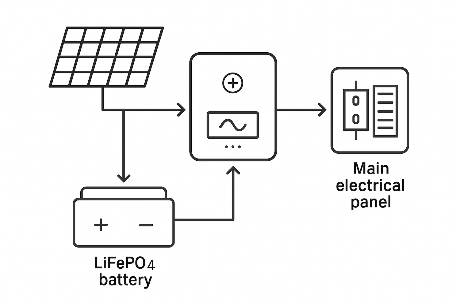
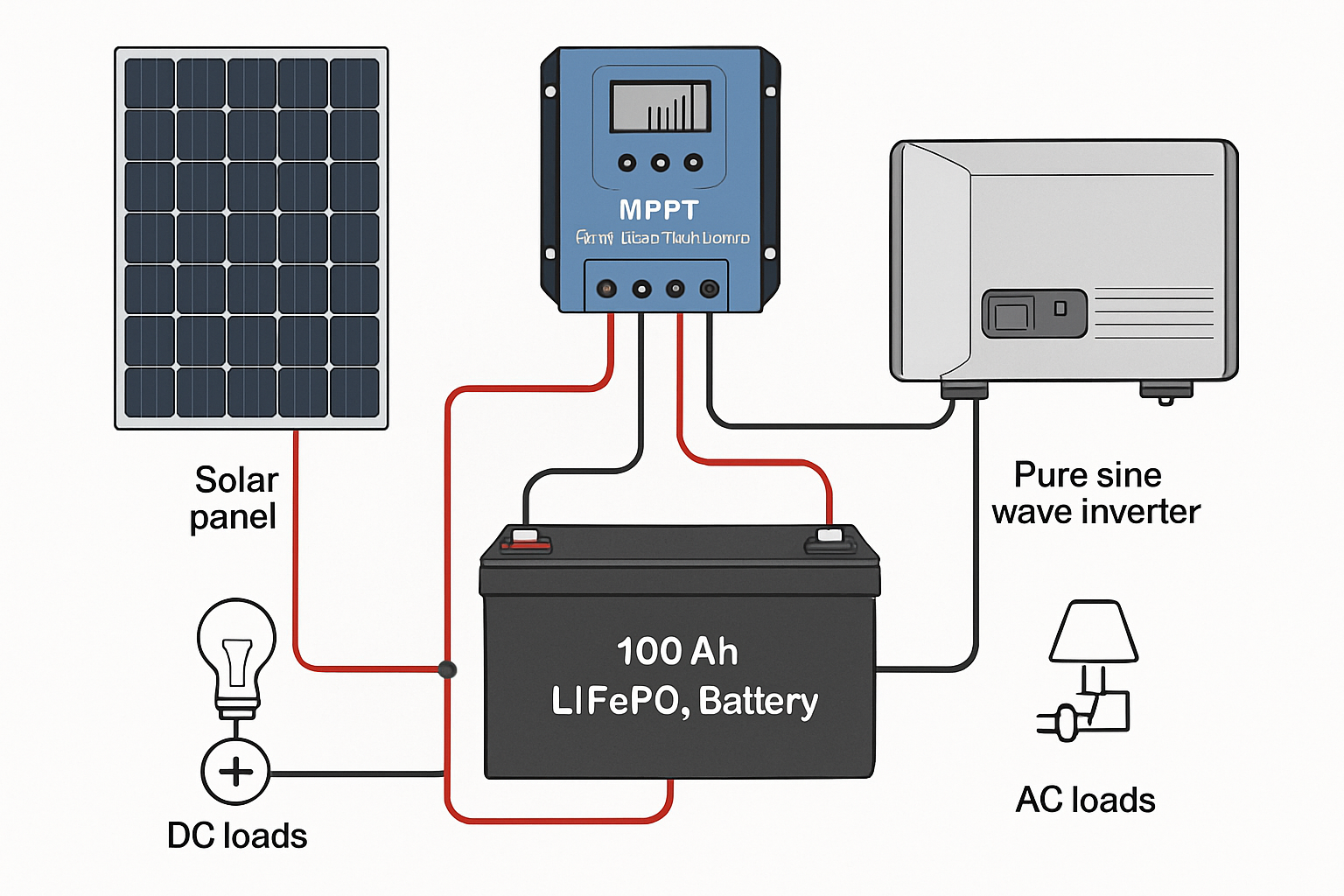
On a diagram, solar panels, or the photovoltaic (PV) array, are typically shown as one or more rectangles. These are the system's generators. Their primary function is to capture sunlight and convert it into direct current (DC) electricity. The diagram will often specify the total wattage of the array, which indicates its power generation capacity under standard test conditions.
The Inverter: The Heart of the System
The inverter is a central component, usually represented as a square or rectangular box. It performs the critical task of converting the DC electricity from the solar panels and battery into alternating current (AC) electricity. AC power is the standard used by household appliances. Hybrid inverters are particularly important in storage systems, as they can manage power flow between the solar panels, the lithium battery, and the electrical grid.
Lithium Battery Storage: Your Energy Reservoir
The battery is your personal energy reservoir, symbolized by a battery icon with positive (+) and negative (-) terminals. It stores excess solar energy generated during the day for use at night or during a power outage. Modern systems frequently use Lithium Iron Phosphate (LiFePO4) batteries, such as a 12V 100Ah LiFePO4 lithium battery, known for their safety, long lifespan, and high efficiency. The diagram will indicate the battery's capacity, usually in kilowatt-hours (kWh).
Following the Path of Power
A diagram uses lines and arrows to show the flow of electricity. Tracing these paths helps you visualize how the system operates in different scenarios.
From Sunlight to Socket: Tracing the DC Path
The journey begins at the solar panels. Lines will show the DC power traveling from the PV array to the inverter. Along this path, you will likely see a symbol for a DC disconnect, a safety switch that can shut off the power from the panels. From the inverter, another DC path connects to the lithium battery, allowing the inverter to charge the battery with surplus solar power or draw power from it when needed.
Powering Your Home: The AC Path
Once the inverter converts DC to AC power, a new path emerges. This AC line connects the inverter to your home's main electrical panel or a dedicated critical loads panel. This is how solar energy powers your lights and appliances. In grid-tied systems, this connection also allows excess power to be sent back to the utility grid, a process often managed through net metering.
Interpreting Symbols and Specifications
Solar battery diagrams use a standardized set of symbols to represent different components and characteristics, making them universally understandable.
Common Symbols and Their Significance
Technical diagrams rely on symbols to convey information concisely. Becoming familiar with this visual language is key. A report from the International Energy Agency, Solar Energy Perspectives, highlights that the balance of system (BOS) components, including wiring and protection devices, are critical for a functional PV system. These are all represented by specific symbols.
| Component | Symbol | Description |
|---|---|---|
| Solar (PV) Panel | Rectangle with internal cell lines | Generates DC electricity from sunlight. |
| Lithium Battery | Multiple horizontal lines with + and - | Stores DC energy for later use. |
| Inverter | Box with DC/AC labels | Converts DC power to AC power. |
| Charge Controller | Box with a line to a battery | Regulates power to prevent battery overcharging. Often built into hybrid inverters. |
| AC/DC Disconnect | A switch symbol on the power line | A manual switch to safely de-energize a circuit. |
| Ground | Three descending horizontal lines | A safety connection to the earth. |
Key Specifications to Note
Beyond symbols, diagrams include vital specifications like Voltage (V), Amperage (A), and Kilowatt-hours (kWh). These numbers define the system's capabilities. For example, a battery's kWh rating tells you its total storage capacity. Understanding these metrics is essential for assessing system capabilities. Key performance indicators like a battery's Depth of Discharge (DoD) and cycle life directly influence its usable capacity and longevity, which are crucial factors explained in guides on solar storage performance. These details help determine the real-world value of your energy storage solution.
Grid-Tied vs. Off-Grid System Diagrams
The layout of a diagram can change significantly depending on whether the system is connected to the utility grid. Both designs offer a path toward greater energy control.
Grid-Tied System Diagrams
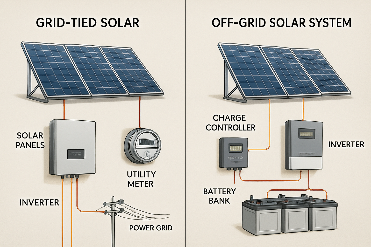
A grid-tied solar battery diagram will always show a connection to the utility grid, typically through a utility meter and the main service panel. This setup allows you to draw power from the grid when your solar generation or battery storage is insufficient and to send excess power back to the grid. The U.S. Department of Energy notes that such systems can enhance grid resilience and support energy security. As described in a success story on the use of microgrids, interconnected systems contribute to a more stable and reliable power infrastructure.
Off-Grid System Diagrams
An off-grid diagram is characterized by its complete separation from the utility grid. In this configuration, the solar panels and the lithium battery bank are the sole sources of power. These systems are self-sufficient, making them ideal for remote locations. The battery system, often a robust 48V LiFePO4 battery setup, is absolutely critical, as it must supply all power needs overnight and during periods of poor weather. The International Renewable Energy Agency's report, Electrification with renewables, often showcases how off-grid solar and storage are vital for providing power to essential services in areas without grid access.
From Blueprint to Reality
A solar and lithium battery storage diagram is more than just a technical drawing; it is a comprehensive map of your energy system. By learning to read it, you gain a deeper understanding of how your system generates, stores, and delivers power. This knowledge is crucial for ensuring your system operates efficiently and safely, putting you in full control of your energy future and paving the way for true energy independence.
Frequently Asked Questions
What is the most important component in a solar and lithium battery system diagram?
While every component is necessary, the hybrid inverter is arguably the most central. It acts as the brain of the system, managing the flow of energy between the solar panels, the lithium battery, your home's loads, and the grid. Its proper function is critical for the entire system's performance.
Why are LiFePO4 batteries often recommended?
Lithium Iron Phosphate (LiFePO4) batteries are frequently recommended for home energy storage due to their superior safety profile, long cycle life, and excellent thermal stability compared to other lithium-ion chemistries. They can typically be discharged more deeply and last for thousands of cycles, offering better long-term value.
Do I need a charge controller if I have a hybrid inverter?
In most modern energy storage systems, a hybrid inverter includes an integrated charge controller, such as an MPPT (Maximum Power Point Tracking) controller. This simplifies the system design and reduces the number of separate components. However, in some custom or older DC-coupled systems, a standalone charge controller may still be used between the solar panels and the battery.


Leave a comment
All comments are moderated before being published.
This site is protected by hCaptcha and the hCaptcha Privacy Policy and Terms of Service apply.