Properly sizing the conductors in your solar photovoltaic (PV) and energy storage system (ESS) is fundamental to its performance and safety. An undersized wire acts like a bottleneck, restricting energy flow and leading to a phenomenon known as voltage drop. This loss of electrical pressure can significantly reduce your system's power output, cause inverters to malfunction, and compromise the overall efficiency of your investment. This text explains the methods for accurate PV and ESS conductor sizing to ensure you capture and use every possible watt of solar energy.
Understanding Voltage Drop in Solar and Storage Systems
Voltage drop is an unavoidable aspect of any electrical circuit, but managing it is crucial. When it becomes excessive, it undermines the very purpose of your solar and storage installation: to generate and store energy efficiently.
What Is Voltage Drop and Why Does It Matter?
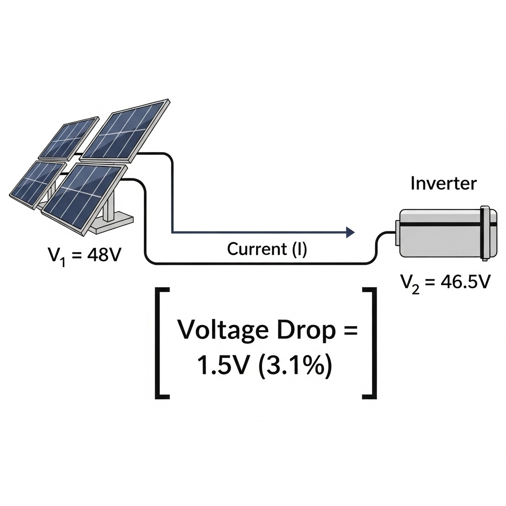
Think of voltage as electrical pressure. Just as water pressure decreases along a very long, thin hose, voltage decreases as it travels through a wire. This decrease is the voltage drop. The energy lost is converted into heat within the conductor. In a solar energy system, this means less voltage—and therefore less power—reaches your inverter or battery bank. The consequences include lower energy harvest, inaccurate battery charging, and potential nuisance trips where the inverter shuts down because it detects a voltage outside its operational window.
Key Factors Influencing Voltage Drop
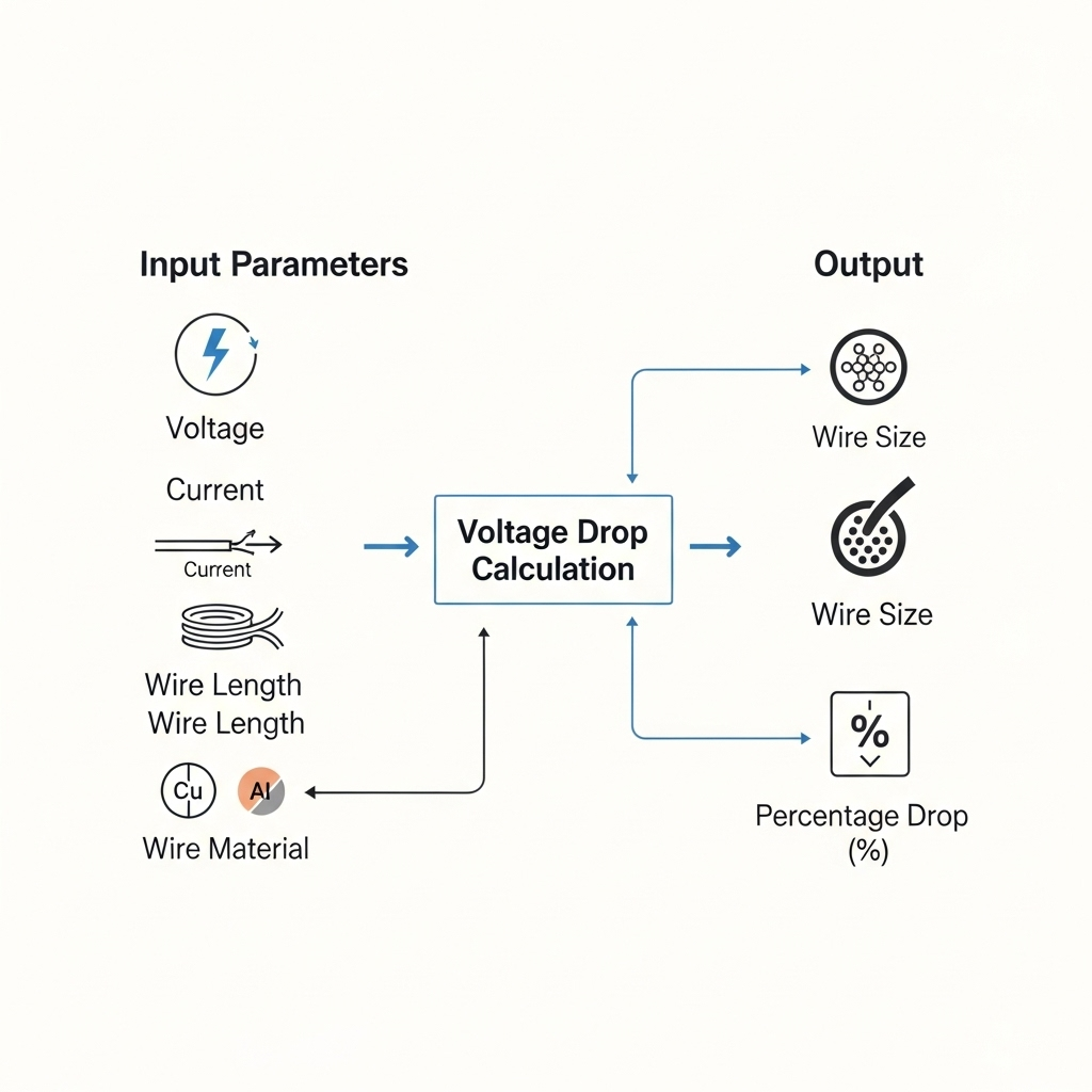
Several variables contribute to the amount of voltage lost in a circuit. Understanding these is the first step in proper PV conductor sizing and ESS conductor sizing.
- Conductor Length: The longer the wire, the greater the total resistance and the more voltage is lost.
- Conductor Size (AWG): A thicker wire (lower American Wire Gauge or AWG number) has less resistance, reducing voltage drop.
- Current (Amperage): Higher currents flowing through a conductor will result in a greater voltage drop. This is especially important for high-power ESS connections.
- Conductor Material: Copper has lower resistivity than aluminum, making it a more efficient conductor. For the same size, a copper wire will have less voltage drop than an aluminum one.
- Temperature: As a conductor's temperature rises, so does its resistance. This is a critical consideration for systems installed in hot climates or enclosed spaces.
The Core Formulas for Conductor Sizing
Accurate conductor sizing isn't guesswork; it's based on established electrical principles and formulas. Using the right voltage drop calculation ensures your system remains efficient and reliable for years to come.
Calculating Voltage Drop: The Essential Equation
The foundational principle is Ohm's Law (V = I × R), where voltage drop (V) equals current (I) multiplied by resistance (R). For practical system design, a more direct formula is used for DC circuits:
Voltage Drop (VD) = (2 × K × I × L) / CM
Where:
- K: Represents the resistivity of the conductor material. For copper, 'K' is approximately 12.9 ohms-cmil/ft.
- I: Is the current in amperes (A).
- L: Is the one-way length of the conductor in feet (ft). The '2' in the formula accounts for the round-trip path of the current.
- CM: Is the cross-sectional area of the conductor in circular mils, which corresponds to its AWG size.
Applying Electrical Code Standards
Industry best practices, often guided by the National Electrical Code (NEC), recommend keeping voltage drop to a minimum. For PV source circuits, a voltage drop of 2% to 3% is a common target. This ensures the inverter receives a stable voltage within its optimal operating range, maximizing power conversion. Failing to meet these standards can lead to significant energy losses over the life of the system.
Sizing Conductors for PV and ESS Applications
The process for sizing conductors varies slightly between the PV array and the energy storage components due to their different operating characteristics, specifically the current they handle.
Step-by-Step Sizing for PV Array Circuits
Let’s consider a 48V PV array located 100 feet from its charge controller, producing 20 amps of current. The goal is to keep the voltage drop below 2%. A 2% drop on a 48V system is 0.96V.
Using the formula, we can rearrange it to solve for the required circular mils (CM):
CM = (2 × 12.9 × 20A × 100 ft) / 0.96V = 53,750 CM
Consulting an AWG chart, a 3 AWG wire (52,620 CM) is slightly too small, so you would select the next larger size, a 2 AWG wire (66,360 CM), to meet the target.
Sizing for Energy Storage System (ESS) Connections
Conductors connecting a battery bank to an inverter are typically short, but they must handle very high currents during discharge cycles. Even a small resistance can cause a significant voltage drop, potentially tripping the inverter's low-voltage disconnect. For these connections, minimizing voltage drop to 1% or less is often recommended. Understanding the peak surge currents from your inverter is critical for this calculation. The performance of your entire storage setup hinges on these connections, a topic covered well in the ultimate reference for solar storage performance, which details how different components interact.
Using a Conductor Sizing Table
For quick reference, tables can provide estimates for conductor sizing. The table below shows the maximum one-way distance for different currents and copper wire sizes to maintain a 2% voltage drop in a 48V DC system.
| Current (Amps) | Max Distance (ft) - 10 AWG Copper | Max Distance (ft) - 8 AWG Copper | Max Distance (ft) - 6 AWG Copper |
|---|---|---|---|
| 10A | 38 ft | 60 ft | 96 ft |
| 15A | 25 ft | 40 ft | 64 ft |
| 20A | 19 ft | 30 ft | 48 ft |
| 30A | 13 ft | 20 ft | 32 ft |
Advanced Strategies to Mitigate Voltage Drop
Beyond simply using thicker wires, several system design strategies can effectively manage voltage drop, particularly in installations with long distances.
Increasing System Voltage
One of the most effective methods is to design the system with a higher DC voltage. For the same amount of power (Watts), a higher voltage results in a lower current (since Power = Voltage × Current). A 48V system will have one-quarter of the current of a 12V system delivering the same power. This lower current dramatically reduces voltage drop, allowing for longer wire runs or smaller conductors.
Centralized Component Placement
Thoughtful system layout can also help. Placing the inverter and batteries as close as practical to the PV array minimizes the length of the high-current DC conductors where voltage drop is most critical. This simple design choice can save costs on heavy-gauge copper wire and improve overall system efficiency.
High-Temperature Conductors
In large-scale applications, advanced solutions like high temperature low sag (HTLS) conductors are used to increase power capacity. According to a report by the IEA on System Integration of Renewables, rewiring with such conductors allows for uprating power delivery significantly. While not typical for residential systems, this highlights the importance of conductor technology in managing power flow. Similarly, research from IRENA on Grid Codes for Renewable Powered Systems emphasizes how modern grid components, including smart inverters, contribute to system stability—a stability that begins with properly sized wiring. Another IEA publication, Getting Wind and Solar onto the Grid, further notes that advanced monitoring can reveal additional capacity in existing lines, reinforcing the principle of managing electrical properties effectively.
Final Thoughts on System Efficiency
Controlling voltage drop is not an optional tweak; it is a core component of designing an efficient and durable solar and energy storage system. By applying the correct voltage drop calculation and selecting the appropriate PV system conductor or ESS system conductor, you ensure that the power you generate is delivered where it's needed. Careful planning, from conductor material selection to overall system voltage, paves the way for a reliable solution that helps you achieve greater energy independence.
Frequently Asked Questions
What is an acceptable voltage drop for a PV system?
Generally, a drop of 2-3% is recommended for DC circuits from the panels to the inverter to ensure optimal performance. Exceeding this can lead to significant power loss over the life of the system.
Does voltage drop affect AC circuits too?
Yes, it affects both DC and AC circuits. The principles are the same, but calculations and acceptable percentages might differ. It is important to size conductors correctly for the AC output from the inverter to the main service panel as well.
Can I use aluminum wire instead of copper to save money?
You can, but aluminum has higher resistance than copper. You will need a larger gauge aluminum wire to carry the same current with the same voltage drop as a copper wire. Always check that terminals on your equipment are rated for aluminum (AL/CU) and follow proper installation techniques to prevent oxidation issues.
How does temperature affect my conductor sizing?
Higher ambient temperatures increase a wire's resistance, which worsens voltage drop and reduces its safe current-carrying capacity (ampacity). The NEC provides temperature correction factors that you should apply to your calculations, especially for installations in hot climates or on rooftops.


Leave a comment
All comments are moderated before being published.
This site is protected by hCaptcha and the hCaptcha Privacy Policy and Terms of Service apply.