In the design of an Energy Storage System (ESS), many components demand attention, from the battery chemistry to the inverter's capabilities. Yet, the wiring that connects everything is often treated as an afterthought, specified only to meet minimum safety codes. This approach overlooks a critical factor that directly impacts profitability: voltage drop. Far from being a minor technical detail, voltage drop is a persistent financial drain that can significantly undermine the return on investment of any energy storage project.
Understanding and mitigating voltage drop is not about over-engineering; it is about smart engineering. It ensures that every kilowatt-hour stored is available for use, that expensive equipment operates efficiently, and that the system delivers on its financial promise over its entire lifespan.
The Hidden Costs of Inefficient Wiring
Excessive voltage drop introduces several performance and financial penalties that accumulate over time. These costs are often invisible in daily operation but become substantial when analyzed over the life of the system.
Direct Energy Loss and Reduced Throughput
At its core, voltage drop is energy lost as heat in the conductors. This is a direct result of the wire's inherent resistance. The power lost can be calculated using the formula P = I²R (Power Loss = Current Squared × Resistance). In an ESS, where high currents are common during charging and discharging cycles, these losses can be significant. For example, a 3% voltage drop in a 48V system cycling 15kWh daily translates to over 164 kWh of wasted energy annually. This is energy you paid to generate and store but can never use or sell, directly reducing your ROI.
Inverter Starvation and Performance Degradation
Inverters and charge controllers are designed to operate within a specific voltage window. When the voltage from the battery bank drops significantly due to long or undersized cables, it can fall below the inverter's minimum input threshold. This condition, often called 'inverter starvation,' forces the unit to either reduce its power output to compensate or shut down completely. As noted in research by the International Energy Agency, voltage fluctuations can lead to more frequent disconnections of power resources. This results in intermittent power delivery and prevents the system from dispatching its full rated power, crippling its ability to handle peak loads or maximize self-consumption.
Accelerated Component Aging and Safety Risks
The energy lost to voltage drop is converted into heat. This excess heat raises the operating temperature of conductors, terminals, and connected components. Over time, elevated temperatures can degrade wire insulation, weaken connections, and accelerate the aging of sensitive electronics within the inverter and Battery Management System (BMS). This not only shortens the lifespan of expensive equipment, leading to premature replacement costs, but also creates a potential fire hazard if connections become compromised.
Strategic Conductor Sizing for Maximum ROI
Designing for optimal financial return requires a mindset shift from meeting the bare minimum safety standards to engineering for peak electrical efficiency. This means treating conductor sizing as a critical investment in the system's long-term performance.
Moving Beyond Minimum Code Requirements
Electrical codes are primarily concerned with preventing fires by specifying a minimum conductor size for a given current. They are not designed to guarantee efficiency. A system can be fully code-compliant with a 4% voltage drop, yet that level of loss is detrimental to ROI. A best practice for high-performance ESS design is to target a voltage drop of 2% or less, particularly on the high-current DC side between the batteries and the inverter. This proactive approach costs more upfront in copper but pays dividends through reduced energy waste and improved reliability.
A Practical Sizing Comparison
Consider a common 48V LiFePO4 battery system that needs to deliver 150 amps over a 15-foot one-way distance. The table below illustrates the financial impact of choosing a performance-oriented conductor over a code-compliant one.
| Parameter | Scenario A: Code-Compliant | Scenario B: ROI-Optimized |
|---|---|---|
| Conductor Size (AWG) | 1/0 | 3/0 |
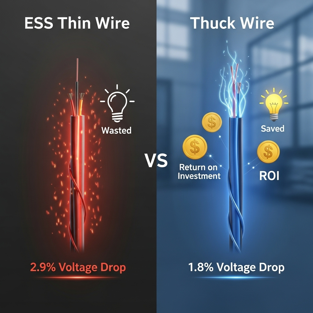
| Voltage Drop (%) | 2.9% | 1.8% |
| Voltage Drop (Volts) | 1.4V | 0.88V |
| Annual Energy Loss* | 115 kWh | 72 kWh |
| 10-Year Energy Loss | 1150 kWh | 720 kWh |
| *Assuming one full 10kWh cycle per day. | ||
While the larger 3/0 cable has a higher initial cost, it saves 430 kWh of energy over ten years. Depending on electricity rates, this saving can easily offset the additional material expense, leading to a higher net return.
Advanced Design Strategies to Mitigate Voltage Drop
Beyond simply using thicker wires, several design strategies can effectively minimize voltage drop and its negative consequences. A holistic approach considers the entire system architecture.
The Advantage of Higher System Voltage
One of the most effective ways to combat voltage drop is to increase the system's nominal voltage. Since power equals voltage times current (P = V × I), doubling the voltage halves the current required for the same amount of power. Because power loss in wires is proportional to the square of the current (P = I²R), halving the current reduces the power loss by a factor of four. This is why commercial-scale systems often use high-voltage battery configurations. For residential and off-grid applications, moving from a 12V to a 48V architecture dramatically reduces current, allowing for smaller, less expensive conductors while keeping losses low.
Optimizing Physical Layout
The physical arrangement of components is a crucial but often overlooked factor. Resistance is directly proportional to the length of the conductor. Therefore, minimizing the distance between the battery bank and the inverter is a primary design goal. A compact layout that reduces cable runs is an effective, no-cost method for reducing voltage drop. The IEA's report, Getting Wind and Solar onto the Grid, emphasizes that a systematic approach to planning is essential for large grids, a principle that holds true for designing efficient micro-level ESS installations.
A Foundation for Lasting Performance
Ultimately, voltage drop is more than a line item in an electrical calculation; it is a direct measure of system inefficiency that erodes financial returns. By prioritizing conductor sizing and intelligent layout during the design phase, you are making a direct investment in the long-term health and profitability of the energy storage system. A system with minimal voltage drop is one that operates reliably, maximizes usable energy, and protects its core components from premature failure. For a more detailed examination of the factors that define system effectiveness, a complete understanding of the metrics behind solar storage performance provides valuable context. As highlighted in the IEA's analysis, Empowering Variable Renewables: Options for Flexible Electricity Systems, maintaining stable system voltage is fundamental to the reliability of modern power systems, from the utility scale down to individual installations.
Frequently Asked Questions
What is an acceptable voltage drop for an ESS?
While electrical codes might permit up to 5%, for optimal performance and ROI, a target of 1-2% on the DC side is a widely accepted best practice in the industry. This minimizes energy waste and prevents issues with inverter operation.
How does temperature affect conductor sizing and voltage drop?
Higher ambient temperatures increase the electrical resistance of a conductor. This means a wire will experience a greater voltage drop and have a lower effective current-carrying capacity (ampacity) in a hot environment. Sizing calculations must account for the highest expected operating temperature to ensure safety and performance.
Is oversizing wires for voltage drop always the best solution?
Not always. While upsizing conductors is a direct solution, it has diminishing returns and increases upfront costs. A more holistic approach is better. First, consider increasing the system's DC voltage, which dramatically lowers current and thus voltage drop. Second, optimize the physical layout to shorten wire runs. Only then, size the conductors to achieve your target 1-2% drop.
Does voltage drop matter on the AC side of the inverter?
Yes, it does. While the currents are typically lower on the AC side for a given power level, significant voltage drop can still occur on long runs to the main service panel or critical loads. This can affect the performance of appliances and cause the inverter to disconnect from the grid if the voltage falls outside of utility standards.
Leave a comment
All comments are moderated before being published.
This site is protected by hCaptcha and the hCaptcha Privacy Policy and Terms of Service apply.