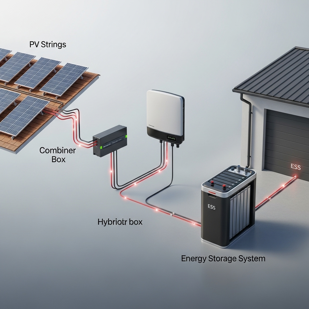
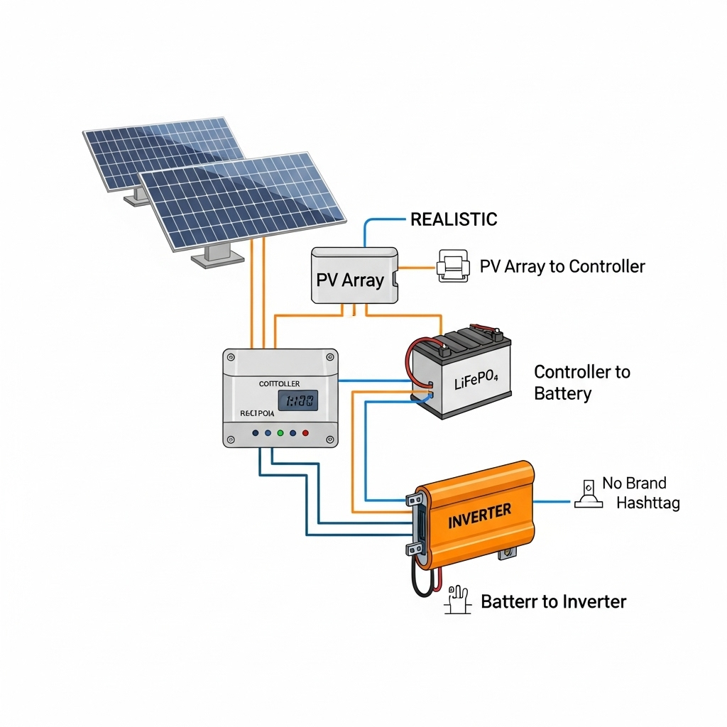
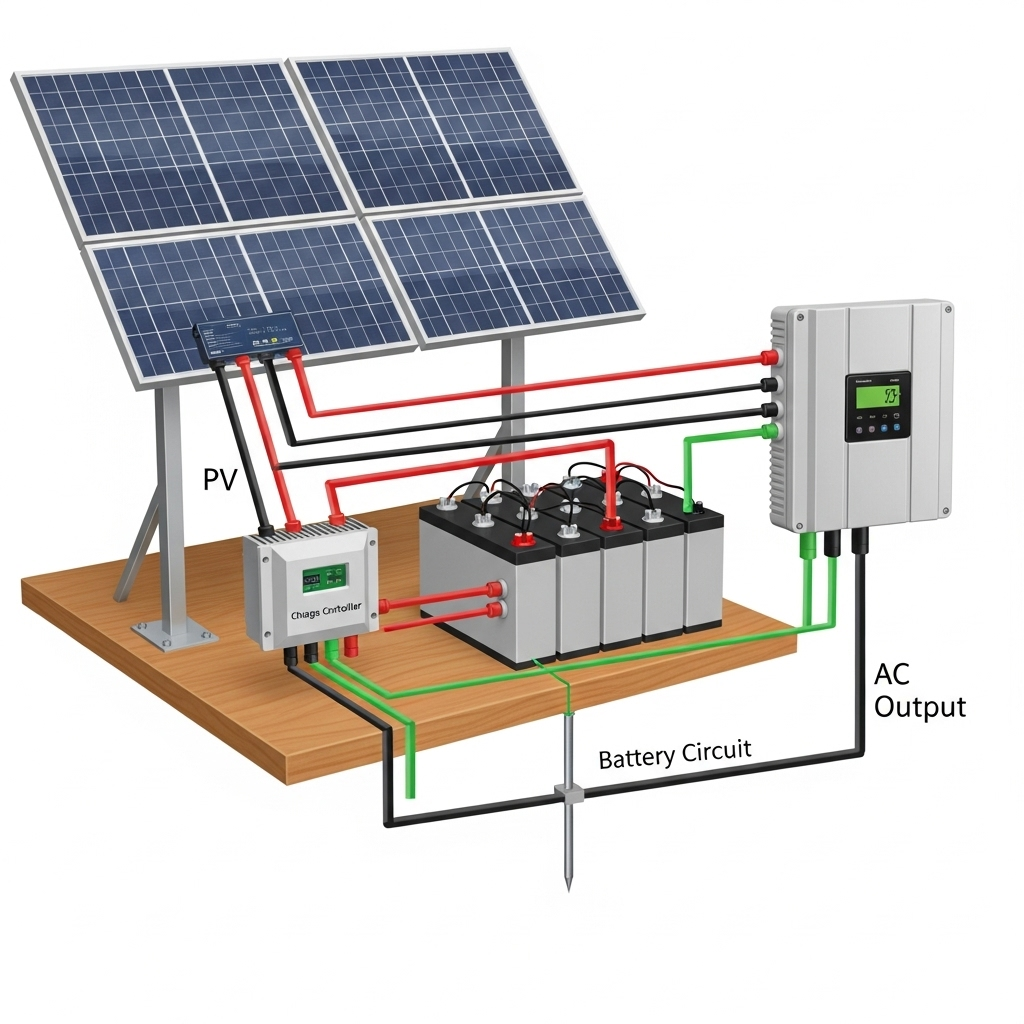
In any solar and energy storage system (ESS), the conductors are the vital arteries that carry power from the point of generation to the point of storage. Yet, an invisible friction exists within these wires: voltage drop. This phenomenon silently chips away at your system’s efficiency, reducing power delivery and potentially impacting equipment performance. Creating a solid wiring blueprint from the photovoltaic (PV) strings all the way to the ESS is fundamental for a reliable and productive energy solution.
The Critical Path: Tracing Power from Sunlight to Storage
Understanding the complete electrical path is the first step in managing voltage drop. The journey involves several distinct segments, each with its own challenges and considerations for conductor sizing.
From PV Strings to the Combiner Box
The process begins with the PV strings, where multiple solar panels are connected in series to build voltage. The current produced here is relatively low, but this is where voltage drop calculations start. Even short runs from the modules to a combiner box contribute to the total loss. Careful planning of array layout can minimize the length of these initial connections, setting a strong foundation for efficiency.
The Homerun to the Inverter
The 'homerun' is the set of conductors that carries the combined DC power from the PV array or combiner box to the inverter or charge controller. This is often the longest wire run in the entire system and, consequently, the most significant source of voltage drop. The length and gauge of these conductors are critical design choices that directly influence how much of the generated power actually reaches your inverter.
Connecting the Inverter to the Energy Storage System
The final link in the DC path is the connection between the inverter or charge controller and the ESS. This segment frequently handles very high currents, especially during periods of high solar production or rapid battery discharge. High amperage makes this connection extremely sensitive to voltage drop. Inadequate conductor sizing here can lead to inefficient charging, reduced battery lifespan, and even cause the inverter to register incorrect battery voltage levels, leading to operational faults.
Calculating and Controlling Voltage Drop
Managing voltage drop is not guesswork; it is a matter of precise calculation and adherence to established limits. A proactive approach prevents power loss and ensures system stability.
The Core Formula and Key Variables
Voltage drop (VD) is calculated with a straightforward application of Ohm's Law. The basic formula is VD = Amps × Resistance. The total resistance of the conductor depends on three main factors: its length, its cross-sectional area (gauge), and the material it's made from (typically copper or aluminum). Longer wires and smaller gauges both increase resistance, which in turn increases voltage drop for a given current.
Establishing Acceptable Limits
For most solar installations, a voltage drop of 2-3% is considered an acceptable limit for the wiring between the PV array and the inverter. For the critical connection between a charge controller and the battery bank, many designers aim for a much stricter limit, often 1%, to maximize charging efficiency. Exceeding these limits means you are converting precious generated electricity into wasted heat within the wires.
Practical Application: A Sizing Example
Consider a 200-foot homerun from a PV array producing 15 amps. The table below illustrates how conductor size (AWG) dramatically affects voltage drop in this scenario, assuming a 48V nominal system.
| Conductor Size (AWG) | Resistance (Ohms/1000ft) | Total Resistance (400ft round trip) | Voltage Drop (Volts) | Percentage Drop |
|---|---|---|---|---|
| 10 AWG Copper | 1.018 | 0.407 | 6.11V | 12.7% |
| 6 AWG Copper | 0.403 | 0.161 | 2.42V | 5.0% |
| 4 AWG Copper | 0.253 | 0.101 | 1.52V | 3.2% |
| 2 AWG Copper | 0.159 | 0.064 | 0.95V | 2.0% |
As the data shows, selecting a 2 AWG conductor over a 10 AWG wire reduces the power loss significantly, bringing it within the desired 2% threshold.
Advanced Strategies for Voltage Drop Management
Beyond simply using thicker wires, several design strategies can effectively and economically manage voltage drop across the entire PV-to-ESS wiring blueprint.
Increasing System Voltage
One of the most powerful tools for reducing voltage drop is to design a system with a higher DC voltage. Since Power = Voltage × Current, doubling the system voltage cuts the current in half for the same power output. This reduction in current directly slashes voltage drop, allowing for longer wire runs or the use of more economical, smaller-gauge conductors. This is a primary reason why commercial systems operate at 600V, 1000V, or even 1500V DC.
Conductor Material and Temperature
While copper is the superior conductor, aluminum offers a lower-cost alternative, particularly for long homeruns. However, aluminum has higher resistance, requiring a larger gauge wire to achieve the same performance as copper. Temperature also plays a crucial role. As conductors heat up, their resistance increases. Sizing calculations must account for the highest likely operating temperatures to ensure performance does not degrade on hot, sunny days. According to research from the IEA, one method for grid optimization involves replacing conductors with ones that can function at higher temperatures, thereby carrying more power. This principle also applies on a smaller scale. The IEA's Getting Wind and Solar onto the Grid report highlights how advanced line monitoring can identify significant additional capacity in existing lines.
Strategic Component Placement
The physical layout of your system components matters. Whenever possible, locating the inverter and ESS closer to the PV array minimizes the length of the high-current DC conductors. Reducing the distance is a direct and effective way to reduce the total resistance in the circuit, thereby minimizing voltage drop without increasing wire cost.
System-Level Planning and Grid Interaction
Effective wiring design extends beyond a single installation, touching on broader concepts of resource management and grid stability, especially as renewable energy systems become more common.
The 'Guitar String' Problem
In larger developments, multiple separate systems may be installed in close proximity. If each system builds its own long connection to a utility substation, it can result in what the International Energy Agency calls a 'guitar strings' configuration—an unnecessary and inefficient duplication of infrastructure. As noted in the IEA's System Integration of Renewables analysis, this can lead to smaller developers being squeezed out due to high connection costs. Coordinated planning can create more efficient, shared connections.
Adhering to Technical Rules
Proper on-site wiring ensures that a solar and storage system operates predictably. This is vital for grid stability. The IEA emphasizes that appropriate technical grid connection rules are critical for ensuring that renewable energy plants do not negatively impact the local quality and reliability of the electricity supply. A well-designed system with managed voltage drop contributes positively to this goal by delivering power reliably and responding correctly to grid signals.
A Blueprint for Performance
A successful wiring plan is more than a set of connections; it is a comprehensive blueprint for efficiency. By carefully tracing the path from PV strings to the ESS, calculating drop at each stage, and implementing smart design strategies like higher system voltages and strategic component placement, you ensure maximum power is captured and stored. Paying close attention to conductor sizing and voltage drop is a defining characteristic of a high-performance renewable energy system. For a comprehensive look at how these details impact overall output, see this analysis of solar and storage performance.
Frequently Asked Questions
What is the maximum recommended voltage drop for a PV to ESS system?
A common industry target is to keep voltage drop below 3% for the entire circuit from the PV modules to the inverter or charge controller. Some designers aim for 2% or even 1% on critical runs, like from the controller to the battery, to maximize charging efficiency.
How does temperature affect my conductor sizing for voltage drop?
Higher temperatures increase the resistance of a conductor. You must account for the highest expected ambient temperature and use correction factors provided by electrical codes. This ensures the wire can handle the current safely and that your voltage drop calculation remains accurate under worst-case conditions.
Can I use aluminum wire instead of copper to save money?
Yes, aluminum can be a cost-effective option, especially for long homerun conductors. However, aluminum has higher resistance than copper for the same size. You must use a larger gauge aluminum wire to achieve the same low voltage drop as a copper equivalent. Also, ensure all connections are made with terminals rated for aluminum to prevent corrosion and failure.
Does a higher system voltage always solve voltage drop issues?
Increasing system voltage is one of the most effective ways to reduce voltage drop because it lowers the current for the same amount of power. For example, doubling the voltage cuts the current in half, which in turn cuts the voltage drop by half. This allows for longer wire runs or the use of smaller, less expensive conductors.


Leave a comment
All comments are moderated before being published.
This site is protected by hCaptcha and the hCaptcha Privacy Policy and Terms of Service apply.