Arc faults in rooftop solar and home storage spark strong opinions. Some think arcs are inevitable and frequent. Others think modern electronics remove the hazard. The truth sits in the middle. You will see what the risk looks like, how detection works, and what actions cut that risk without hurting uptime.
Quick context: where arcs can start in homes
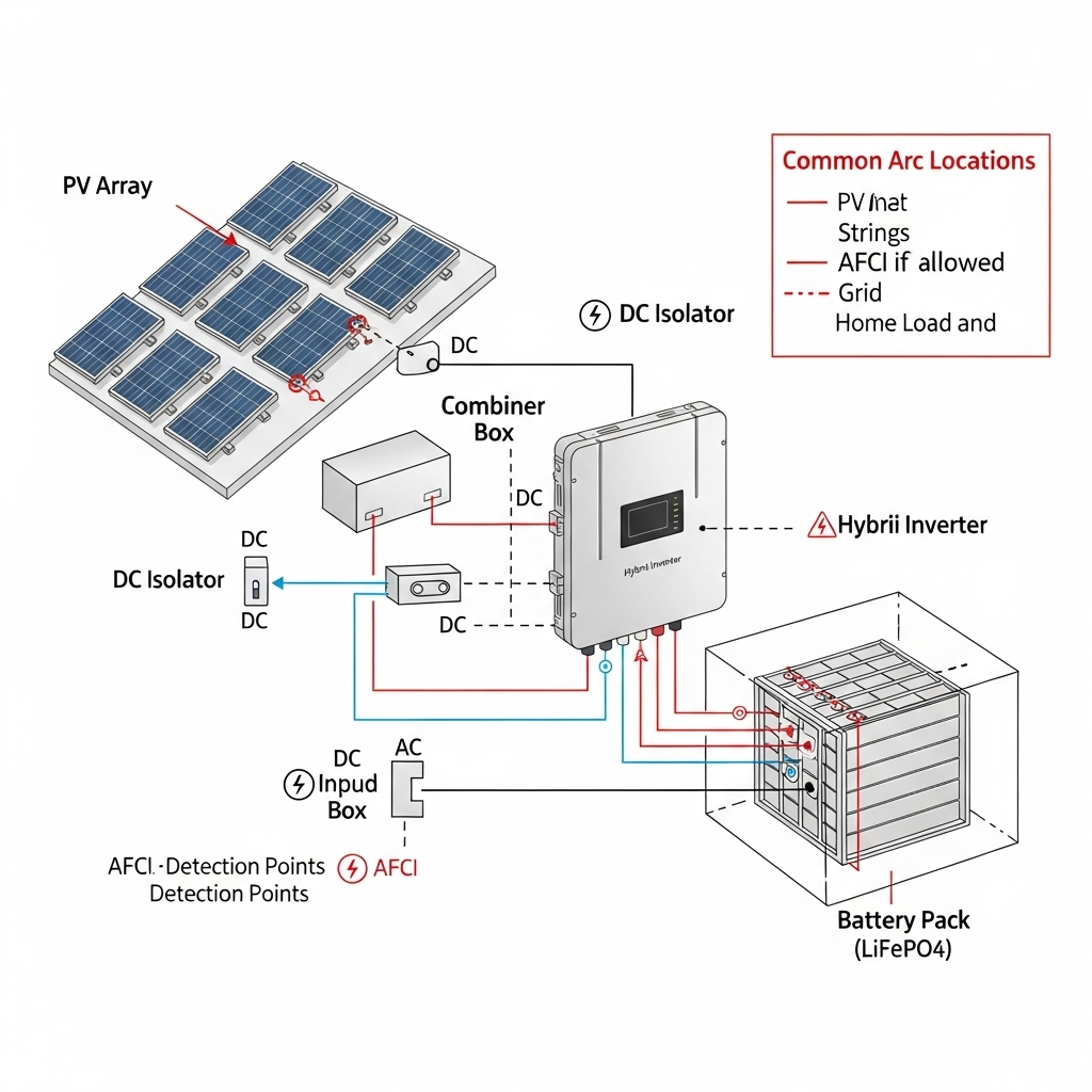
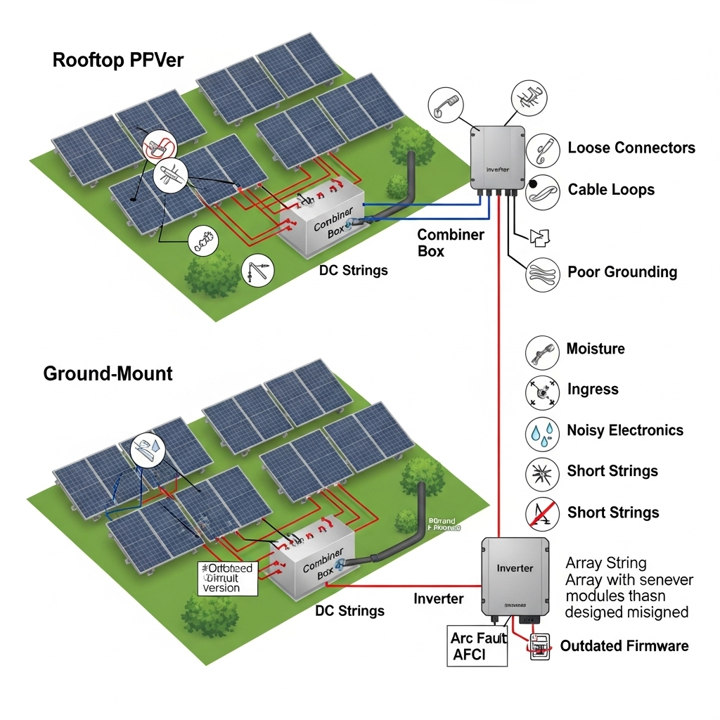
In residential PV, arcs form most often at weak connections. Think mismatched connectors, loose terminals, damaged insulation, or aged DC switches. In hybrid PV+ESS, add battery lugs, internal busbars, and contactors to the list. Inverter inputs and rooftop junction boxes matter too.
Availability loss rises any time the system shuts down for faults or nuisance trips. Reducing ground-fault and arc-fault events, and cutting false trips, improves uptime, as noted by U.S. DOE SETO. The same point appears in sector summaries that track inverter trips and fault-driven downtime.
Myths vs reality you can act on
Myth 1: Arc-faults are common in modern residential PV
Reality: True arc events are rare relative to total operating hours. Large installed bases run for years without a single arc event. Still, the impact can be severe if it happens. Reliable design and tuned detection reduce that already low probability and minimize availability loss. U.S. research notes that improving component reliability and reducing arc-fault and ground-fault trips lifts uptime and yield (SETO Systems Integration and On the Path to SunShot).
Global agencies track fast PV growth, which pushes safety practices forward. See IEA and IRENA deployment data. High deployment with low incident rates signals that prevention and detection are working where designs follow best practice.
Myth 2: AFCI removes all arc risk
Reality: Arc-fault detection is powerful but not perfect. Algorithms look for current and voltage signatures in time and frequency domains. They can miss very stable low-energy arcs or trip on look-alike noise without careful tuning. U.S. codes such as NEC 690.11 and international work such as IEC 63027 define performance goals and shutoff response times. Field experience shows sub-second detection is possible, yet installers still need solid terminations and correct connector mating to cut ignition sources in the first place. DOE documents describe how inverters continue to evolve with better sensing and fault response (SETO 2020).
Myth 3: ESS makes DC arc risk much higher
Reality: Risk depends on architecture. In many homes, storage is AC-coupled. Most DC arc exposure sits on the PV array side, not the battery side. In hybrid inverters with DC-coupled batteries, bus voltages often sit in the 48–120 V range, which can still sustain an arc across small gaps under load. Good news: contactors with pre-charge, correct fusing, and tight lugs keep that risk low. A practical storage performance reference shows how charge/discharge profiles and round‑trip efficiency shape currents and cable sizing, which feeds into safe connector selection (ultimate reference: solar storage performance). Typical LiFePO4 systems run high cycle efficiency and moderate C-rates in homes, limiting thermal stress at terminals.
Myth 4: Low-voltage strings or MLPE remove the hazard
Reality: Lower voltage reduces arc energy but does not take risk to zero. Series arcs can still start at a single loose connector. AC arcs can occur on the load side too. Module-level power electronics (MLPE) do solve mismatch loss in residential PV and can localize issues to a smaller segment, yet installers still need correct crimping, compatible connectors, and strain relief. Industry reviews highlight the value of thermal scans to catch weak spots early (Tsanakas et al., 2016; Haque et al., 2019).
Myth 5: Arcs appear mainly at mid-day, under peak sun
Reality: Many arcs start during transitions. Morning wake-up, intermittent shading, gust-driven connector motion, or switching events in electronics can trigger unstable contacts. Watch these windows during commissioning and O&M testing.
What data says about architecture and risk
The table gives practical ranges seen in homes. Values vary by product and setup; always check device ratings.
| Residential architecture | Typical DC voltage range | Common arc locations | Typical AFCI location | Notes |
|---|---|---|---|---|
| String inverter PV | 300–600 Vdc (some up to 1,000 Vdc in larger homes) | Module leads, connectors, combiner, DC isolator, inverter DC input | Inverter input (DC), sometimes string-level | Higher voltage sustains arcs more easily; strong need for connector quality |
| MLPE (micro/optimizer) | Per-module DC 30–60 Vdc; AC bus at 240 Vac | Module connectors, trunk cables, AC junctions | Inverter-side algorithms; module-level shutdown features | Lower per-string DC energy, but poor connections can still arc |
| Hybrid inverter with DC-coupled ESS (LiFePO4) | Battery 48–120 Vdc; PV input 300–600 Vdc | Battery lugs, busbars, contactor, PV connectors | Inverter DC input; some battery-side protection | Pre-charge and correct torque reduce battery-side arcing risk |
| AC-coupled ESS | Battery internal DC 48–120 Vdc; PV DC as above | AC breakers, terminals, PV connectors | Inverter AFCI on PV side; AC protection for ESS | Arc exposure split across PV DC and home AC circuits |
Why does this matter? Because availability loss ties directly to trips. Energy-sector sources note that inverters can trip for ground faults or arc faults, and reducing both faults and false trips improves uptime (On the Path to SunShot). Better detection and smarter inverters are part of that trend (SETO 2020).
Detection: what works in homes
- Use inverters with robust AFCI tuned for residential string lengths and local noise. Ask for detection response data and false-trip mitigation features.
- Commissioning tests help. Induce switching events, irradiance ramps, and appliance cycling to see if detection stays stable. Record waveforms if the inverter supports it.
- Thermal scans catch loose joints before they heat up under peak current. Studies review infrared thermography for PV fault finding (Tsanakas et al., 2016).
- Plan maintenance around seasons. Temperature swings and UV aging change cable stiffness and clamp force. Short visual checks prevent many issues.
Mitigation that actually reduces risk
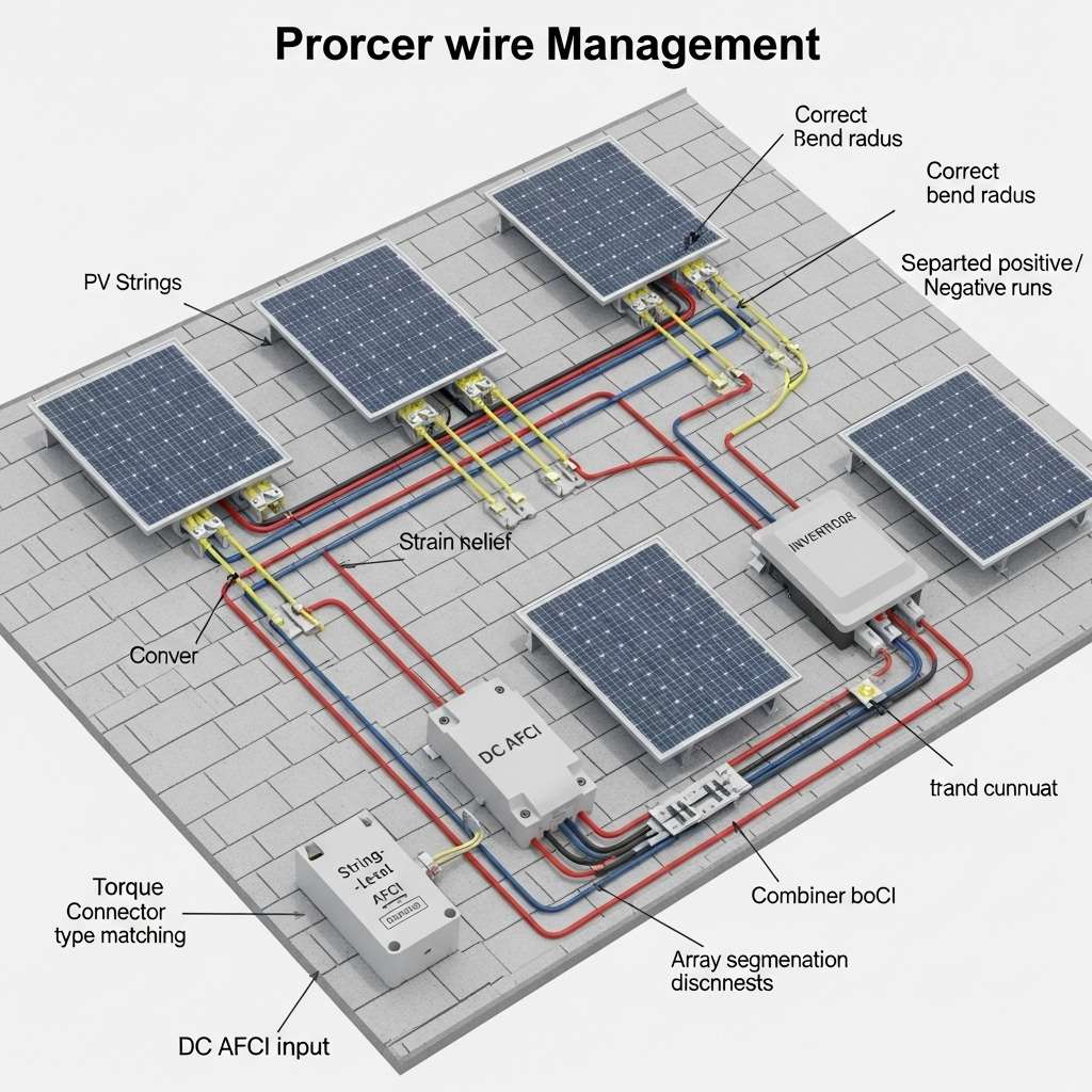
- Keep connectors from the same series and rating. Do not mix look‑alike plugs. Follow the crimp tool and die specified by the connector maker.
- Document torque values. Use a calibrated wrench for battery lugs, busbars, and DC isolators. Re‑torque during the first seasonal check.
- Route cables with strain relief and UV‑rated ties. No sharp bends. Keep connectors out of water paths.
- Specify DC switches and fuses with correct voltage and breaking capacity. Battery circuits benefit from contactors with pre‑charge to prevent inrush sparks.
- Update firmware. Inverter and ESS vendors improve AFCI algorithms and noise rejection over time.
- Train crews. Workforce programs show that targeted training boosts build quality and safety culture. See sector efforts summarized by National Solar Jobs Census.
What changing grids add to the picture
High levels of inverter-based resources change fault behavior and protection settings. Classic protection schemes relied on high fault current and its direction, which can be limited with PV inverters. U.S. analysis highlights how grid-following inverters keep adding capabilities, including improved visibility and controllability (SETO 2020). This trend supports safer, more reliable operation across millions of small systems tracked by EIA and global agencies.
Storage performance data that informs safety
Storage duty cycles set cable temperature rise and connector stress. A practical field reference compiles storage round‑trip efficiency and discharge behavior across use cases, helping teams size conductors and set protection with real numbers (ultimate reference: solar storage performance). Combine that with DOE reliability themes on availability loss, and you have a data‑based way to choose correct cable gauges, lugs, and AFCI settings for your PV ESS.
Key takeaways
- Arc-fault risk in residential PV+ESS is real but manageable. The largest wins come from build quality and stable detection.
- False trips hurt availability. Tuning and firmware updates, backed by field tests, reduce nuisance events and protect yield.
- ESS does not automatically raise risk. Architecture and workmanship decide the outcome.
Energy agencies and labs continue to publish methods to lift reliability and safety. See Energy.gov Solar Energy for programs, and deployment views from IEA and IRENA.
Safety and compliance note
Informational only, not safety or legal advice. Codes update over time. Work with a licensed electrician and your AHJ for permits, inspections, and local code details.
FAQ
Does adding a home battery make AFCI tuning harder?
Sometimes. Hybrid inverters introduce extra switching states that can look noisy. Ask for residential AFCI profiles and run a commissioning test with charge and discharge active.
Can AC-side issues trigger a DC arc-fault trip?
AC noise can couple into measurements, yet good algorithms filter that out. Quality grounding and clean routing reduce cross-coupling.
What non-invasive signs suggest arc risk?
Frequent intermittent production drops, audible crackling near a combiner, or a connector that feels warmer than nearby parts. Use thermal scans to confirm.
How often should I check connectors and lugs?
Do a visual check after the first season, then annually. Re‑torque lugs per maker specs. Schedule scans ahead of summer peaks.
Do bifacial modules change residential arc risk?
Bifacial mainly affects energy yield via layout, tracker design, and albedo. Safety still hinges on connectors, routing, and AFCI. See design factors summarized in sector research that links spacing, height, and reflectivity to yield.


Leave a comment
All comments are moderated before being published.
This site is protected by hCaptcha and the hCaptcha Privacy Policy and Terms of Service apply.