


DC arcs start small and escalate fast. Good wiring design lowers the chance of ignition. A fit-for-purpose AFCI strategy cuts energy and time to clear faults. This piece focuses on layout, materials, and detection choices that reduce PV and hybrid ESS risk without adding avoidable cost.
Why wiring choices shape DC arc risk
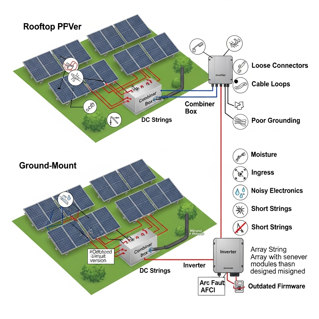
Arcs in PV circuits usually start at weak points: loose terminations, mismatched connectors, damaged insulation, or abrasion at roof edges. Voltage in modern arrays is high enough to sustain an arc once it strikes, so prevention is the priority.
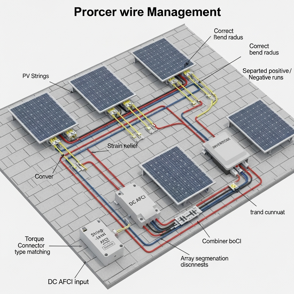
- Connectors and crimps: Use only matched connector families and certified tools. Verify conductor insertion depth and crimp height. Add ferrules where screw terminals are used.
- Torque and strain: Torque lugs to manufacturer spec and recheck after thermal cycling during commissioning. Provide strain relief so connectors are not bearing cable weight.
- Routing and protection: Keep conductors off sharp edges. Use UV-rated clips at 300–600 mm spacing. Add grommets at all metal pass-throughs. Separate positive and negative in parallel runs to reduce rubbing and EMI.
- Insulation and ratings: Use PV wire with wet-rated 90°C or better insulation and correct voltage class. Avoid micro-bending that can crack insulation over time.
Where inverter-based resources dominate, fault currents are limited. Protection based only on current magnitude can miss early-stage arcs. Research summarized by power-system bodies points to time-domain and non-magnitude signatures to detect faults reliably in such grids. See the discussion of adaptive protection and time-domain signatures in the IEA report The Power of Transformation and related work funded by ARPA‑E.
Wiring design patterns that cut ignition probability
Array voltage class and segmentation
Higher voltage boosts arc sustainment. Limit exposed length energized at any time. Use section isolators and clear labeling to speed troubleshooting.
| PV system class | Typical max string voltage | Design notes for DC arc risk |
|---|---|---|
| Residential | Up to 600 Vdc (region specific) | Short home-run cables; place combiner near array to limit energized length. |
| Commercial & Industrial | Up to 1000 Vdc | Segment arrays with rooftop disconnects; maintain conductor separation and strain relief on long trays. |
| Utility-scale | Up to 1500 Vdc | Use string monitoring and string-level protection; enforce strict connector QA to avoid parallel arc paths. |
Harness layout and EMI discipline
- Keep parallel runs in trays separated by dividers to limit crosstalk that can confuse arc-fault detection methods.
- Twist home-run pairs lightly or keep consistent spacing to reduce loop area and radiated noise.
- Avoid tight bundles near power electronics. Reserve space for DC filters and ferrites if site noise proves high.
Bonding and grounding
- Bond all metallic racking to one equipotential grid. Verify continuity across splices.
- Use low-impedance paths for fault currents so protective devices see a clear signature.
Quality assurance matters. Requiring certified components aligned with IEC/UL reduces hidden failure modes, as emphasized in IRENA guidance on quality infrastructure for smart mini-grids.
AFCI strategy that actually reduces risk
Placement options
Choose where detection and interruption happen. Each location has trade-offs in sensitivity, selectivity, and cost.
| AFCI location | Pros | Trade-offs | Good fit |
|---|---|---|---|
| Inverter DC input (integrated) | Simple wiring; one device to maintain; coordinated with inverter controls | Lower granularity; may struggle to localize faults far from the inverter | Residential and small C&I with short home runs |
| String-level in combiner | High sensitivity; better localization; fewer nuisance trips with per-string thresholds | More devices; added wiring complexity and cost | Large rooftops and 1000–1500 Vdc fields |
Detection methods and tuning
- Signature types: Combine current ripple, high-frequency noise, and dV/dt events across 10 kHz–500 kHz bands. Blend features to reduce false positives from switching noise.
- Cross-correlation: Compare signatures across strings. Real arcs affect one string; inverter switching affects many equally.
- Time-domain focus: In IBR-dominant systems, limited fault current makes magnitude-only schemes weak. Time-domain features and traveling-wave cues improve sensitivity, aligning with adaptive protection concepts referenced by the IEA (report link).
- Trip logic: Use two-stage logic: fast pre-trip in 50–200 ms, confirm within 0.5–2 s with a different feature set, then open DC. This keeps speed high without spurious trips.
Communications help. Direct transfer trip between combiner and inverter, and coordinated thresholds, reflect broader grid protection trends such as communication-assisted schemes highlighted in the IEA report. For background on solar safety practices and training resources, see U.S. DOE Solar Energy.
Storage-aware wiring and AFCI integration
Hybrid systems add batteries and DC buses that can mask or mimic arc signatures. Coordinate wiring and thresholds across PV and storage.
- DC bus layout: Physically separate PV strings, battery leads, and DC-link capacitors. Shorten high di/dt loops near the inverter to limit conducted noise entering AFCI sensors.
- Filter design: Size input filters so switching ripple from the inverter does not sit in the same band as arc noise. Validate during commissioning with a portable spectrum analyzer.
- ESS performance context: Practical storage performance figures guide ride-through and trip delay choices. As summarized in the Ultimate Reference to Solar & Storage Performance, LiFePO4 systems often reach round-trip efficiency near the mid-90% range and deliver multi‑thousand cycle life at moderate depth of discharge. That supports design targets that avoid frequent hard shutdowns and keep battery cycling gentle.
Grid research also notes reduced fault current with high inverter penetration, challenging magnitude-based protection. This reinforces the case for non-magnitude detection features and adaptive settings in DC protection, a theme echoed in industry literature and DOE-funded work. See DOE Solar Energy for safety program materials.
Commissioning and maintenance that prevent arcs
Acceptance tests
- Visual and torque audit: Verify every connector latch, seal, and torque. Record values.
- Insulation resistance: Test strings with a megohmmeter at appropriate voltage. Investigate any conductor-to-rail leakage.
- IV-curve and thermal scans: Look for mismatch, hot spots, and hidden resistive joints that can evolve into arcs.
Data and KPIs
- Track nuisance-trip rate, confirmed arc events, and time-to-clear. Keep a per‑MW metric to compare sites.
- Log noise bands observed during normal operation to inform AFCI filter updates.
Weather resilience and uptime
Extreme winds and grid outages can stress components and lock controls without backup power. IRENA’s analysis on extreme weather calls for backup supplies that keep yaw or pitch systems alive in wind plants; the same mindset applies to PV safety controls. Maintain backup power for rapid shutdown and AFCI modules so safety functions remain active during outages. Secure harnesses for storm loads and inspect for hidden fatigue after events.
Practical checklist
- Use matched connectors and certified crimp tools; document torque.
- Route conductors with edge protection, correct spacing, and strain relief.
- Segment arrays and place disconnects to limit energized length.
- Choose AFCI location to match array size; set two-stage trip logic.
- Tune filters so inverter ripple does not overlap arc bands.
- Commission with IR, IV-curve, insulation tests, and HF noise capture.
- Keep safety power available during outages; inspect after severe weather.
Standards and compliance are vital to safe deployment and bankability. Policy and system-integration reports from groups like the IEA and IRENA provide credible context for protection strategy design (IEA, IRENA, IRENA). For market growth data and safety awareness, see EIA and DOE Solar Energy.
Code and compliance note (non-legal advice): Align designs with current electrical codes in your region and applicable product standards. Validate AFCI certification scope and test limits for the intended voltage class.
FAQ
What is the difference between series and parallel DC arcs?
A series arc forms in-line with current flow, often from a loose connector or broken conductor. A parallel arc bridges conductors or conductor-to-ground. Parallel arcs can draw higher current and damage gear faster. Both can start from small resistive faults that heat up over time.
Does 1500 Vdc make DC arcs more likely?
Higher voltage does not cause a fault by itself, but it helps sustain an arc once it strikes. That is why connector quality, layout, and fast detection are so important at 1000–1500 Vdc.
Can AFCI fully prevent PV fires?
No device removes all risk. A well-tuned AFCI limits arc energy and shortens fault duration. Combined with careful wiring, the risk drops substantially.
What commissioning tests catch arc-prone points early?
Do a torque audit, insulation resistance tests, IV-curve checks, and thermal imaging. Review high-frequency noise with a portable analyzer to set clean AFCI thresholds.
How does storage affect AFCI settings?
Hybrid systems add switching noise and new current paths. Separate wiring physically, add filtering, and set thresholds using site noise data. Use storage performance data to choose sensible ride-through delays.

Leave a comment
All comments are moderated before being published.
This site is protected by hCaptcha and the hCaptcha Privacy Policy and Terms of Service apply.