The solar inverter is the heart of your energy system, diligently converting DC power from your panels into usable AC power for your home. Its performance dictates not only your system's efficiency but also its long-term reliability. Two critical, yet often overlooked, performance metrics are Total Harmonic Distortion (THD) and surge immunity. A failure in either area can lead to poor power quality, damage to sensitive electronics, or complete system failure. This blueprint provides the essential design and selection criteria for securing an inverter that excels on both fronts, ensuring a clean, stable, and durable power supply.
Understanding the Core Pillars: THD and Surge Immunity
Before diving into design specifics, it's crucial to grasp what these terms represent and why they are fundamental to your system's health. They are the twin pillars supporting the power quality and resilience of your solar installation.
What is Total Harmonic Distortion (THD) and Why Does It Matter?
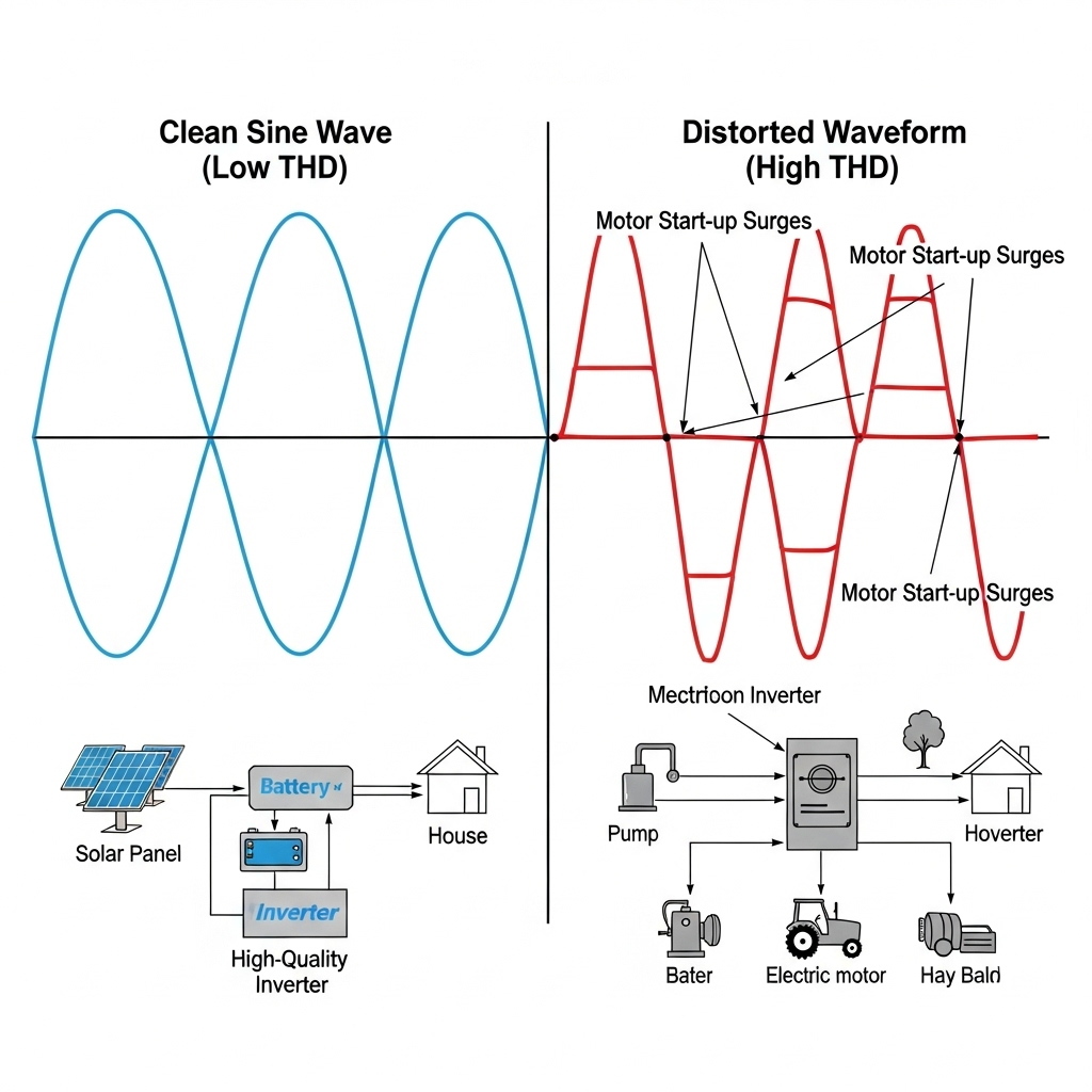
Total Harmonic Distortion is a measurement of the distortion in an AC waveform compared to a perfect sine wave. In simple terms, it's electrical 'noise'. This noise is generated by the inverter's power electronics during the DC-to-AC conversion process. High THD can cause a host of problems, including overheating in wiring, audible humming from appliances, and malfunctions or permanent damage to sensitive electronic devices like computers and modern appliances. Utility grids have strict requirements, often demanding THD levels below 5% to maintain grid stability.
The Hidden Threat: Power Surges and Their Origins
Power surges are brief but powerful increases in voltage. While often associated with direct lightning strikes, most surges originate from less dramatic sources like utility grid switching, the cycling of large motors in nearby industrial facilities, or even large appliances turning on and off within your own home. These transient overvoltages can degrade and destroy an inverter's delicate internal components, leading to costly and unexpected system downtime.
Design Principles for Minimizing Total Harmonic Distortion
Achieving a clean, low-THD output is not accidental; it is the result of deliberate engineering choices in inverter topology, component quality, and system configuration. A well-designed inverter actively filters and shapes the AC waveform to be as pure as possible.
Advanced Inverter Topology and Control Algorithms
Modern inverters move beyond simple conversion. Advanced designs often use a multi-level topology, which generates a stepped AC waveform that more closely resembles a pure sine wave from the outset. This significantly reduces the filtering required. This output is then refined by sophisticated Pulse Width Modulation (PWM) control algorithms. These algorithms, run by fast digital signal processors, make thousands of adjustments per second to actively cancel out harmonic distortions and produce a clean, stable output.
The Critical Role of High-Quality Components
The passive components within an inverter are fundamental to filtering out harmonic noise. High-quality, properly sized inductors and capacitors form an L-C filter that smooths the final AC waveform, acting as the last line of defense against THD. Furthermore, the choice of switching transistors, such as Insulated-Gate Bipolar Transistors (IGBTs), plays a role. Higher-grade IGBTs that can switch faster and more efficiently generate less distortion during the conversion process, contributing to a cleaner overall output.
Optimizing the Inverter Load Ratio (ILR)
The Inverter Load Ratio (ILR), which is the ratio of the solar panel array's DC power rating to the inverter's AC power rating, also influences performance. According to the International Energy Agency's Next Generation Wind and Solar Power report, optimizing this ratio is a key strategy for increasing the value of the energy generated. An improperly sized ILR can force the inverter to operate outside its most efficient range, which can increase thermal stress and, consequently, elevate THD levels.
Engineering Robust Surge Immunity into Solar Inverters
An inverter's ability to withstand power surges is a direct measure of its durability. Robust protection is built-in through a combination of dedicated protective devices, intelligent physical layout, and fortified components.

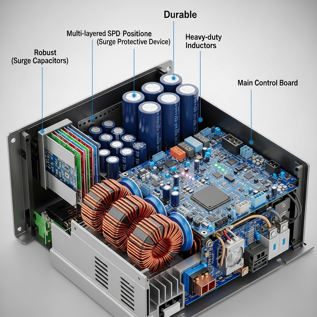
A Multi-Layered Defense: Integrated Surge Protective Devices (SPDs)
The primary defense against surges is the Surge Protective Device (SPD). High-quality inverters incorporate SPDs directly onto both their DC and AC circuit boards. This is a multi-layered defense system, often using a combination of Metal Oxide Varistors (MOVs) to clamp high-voltage spikes and Gas Discharge Tubes (GDTs) to divert large amounts of surge current safely to the ground. This integrated protection is the first and most critical barrier against external electrical events.
Physical Design and Component Fortification
Thoughtful physical design provides passive surge protection. This includes ensuring adequate spacing (creepage and clearance) between conductive paths on the circuit boards to prevent high-voltage arcing. Beyond layout, specifying components like capacitors and inductors with voltage ratings significantly higher than what is required for normal operation provides a crucial safety margin. This fortification ensures that components are not operating at their absolute limit, making them less susceptible to damage from overvoltage events.
The Foundation of Protection: Grounding and Wiring
An inverter’s internal surge protection is only as good as its connection to the ground. A low-impedance grounding system is non-negotiable. It provides a safe path for surge currents to dissipate, preventing them from flowing through and destroying sensitive electronics. Proper wiring practices, including using the correct wire gauge and routing DC and AC wiring separately, further reduce the system's susceptibility to surges.
The Synergy Between Efficiency Curves, THD, and Surge Handling
A truly superior inverter is not defined by a single specification but by how its various performance characteristics work together. Efficiency, distortion, and durability are deeply interconnected.
Why Peak Efficiency Isn't the Whole Story
Manufacturers often advertise an inverter's 'peak efficiency,' a rating achieved only under ideal laboratory conditions. In reality, a solar system operates under partial load for much of the day. An inverter with a flat efficiency curve—meaning it maintains high efficiency across a wide range of loads—indicates a more advanced design. This superior part-load performance often correlates with better thermal management and lower component stress, which in turn contributes to consistently low THD and enhanced resilience against surges.
Analyzing Performance Data for a Holistic View
When selecting an inverter, you must look beyond the headline numbers. A holistic analysis of the datasheet reveals the true quality of the unit. For a deeper look into evaluating these metrics, the ultimate reference on solar storage performance provides detailed methodologies for comparing system components. Consider the following comparison:
| Specification | Inverter A | Inverter B |
|---|---|---|
| Peak Efficiency | 98.5% | 98.0% |
| CEC/European Efficiency | 97.5% | 97.8% |
| THD (Full Load) | < 4% | < 2% |
| Integrated SPD Type | Type 3 | Type 2 (DC & AC) |
| Surge Current Rating | 10 kA | 25 kA |
Here, Inverter A has a slightly higher peak efficiency, but Inverter B shows superior real-world efficiency (CEC/European), significantly lower THD, and much more robust surge protection. Inverter B is the clear choice for long-term reliability and power quality.
Building for a Resilient Energy Future
Constructing a solar energy system that is both powerful and durable requires looking past surface-level specifications. By prioritizing inverters engineered with advanced topologies, high-quality components, and a multi-layered approach to surge protection, you lay the foundation for a truly resilient system. This blueprint—focusing on low THD and robust surge immunity—is your guide to achieving clean, stable, and uninterrupted power, securing your investment and advancing your journey toward energy independence.
Frequently Asked Questions
What is a good THD value for a solar inverter?
Less than 5% is generally required by utilities to connect to the grid. However, premium solar inverters often achieve THD values of less than 3% or even 2% under typical operating loads, ensuring higher power quality for your sensitive electronics.
Can an external SPD be added to an inverter?
Yes, and it is highly recommended. Even if your inverter has robust internal SPDs, adding external, higher-rated SPDs at your main service panel (Type 1) and at the solar array's DC combiner box provides a layered defense that offers the highest level of protection against severe surges.
Does a higher inverter surge rating always mean it's better?
A higher surge current rating, measured in kiloamperes (kA), indicates a greater capacity to handle a large surge. While a higher kA rating is generally better, it's also important to consider the clamping voltage (the voltage at which the SPD activates) and whether the protection is multi-stage. A comprehensive protection scheme is more important than a single high number.
How does operating temperature affect THD and surge susceptibility?
High operating temperatures place stress on all electronic components. This stress can lead to increased electronic noise and higher THD. It can also degrade components over time, making them more vulnerable to failure during a surge event. Inverters with superior thermal management systems, like those with large heat sinks and variable-speed fans, maintain better performance and reliability.
Leave a comment
All comments are moderated before being published.
This site is protected by hCaptcha and the hCaptcha Privacy Policy and Terms of Service apply.