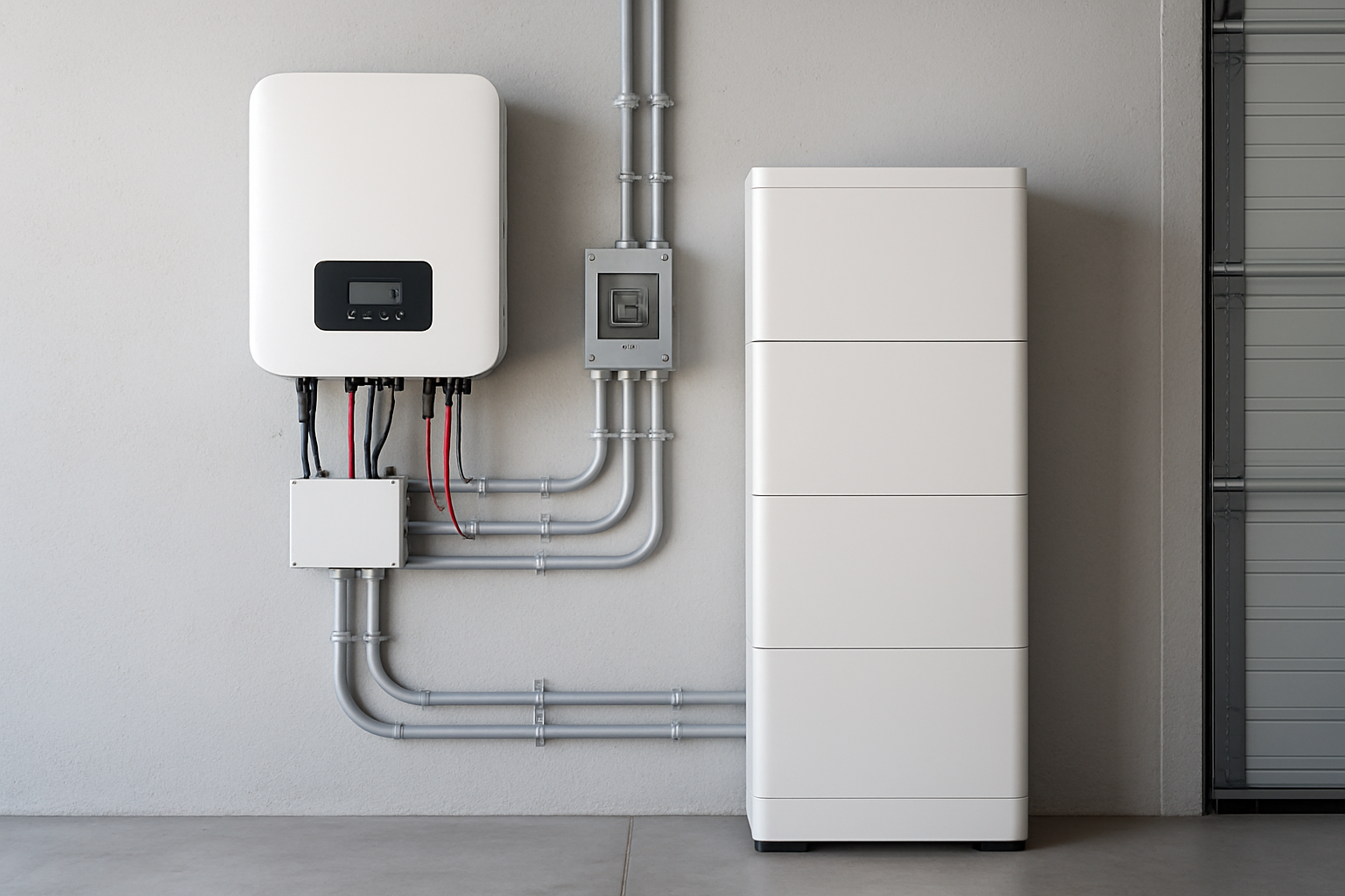
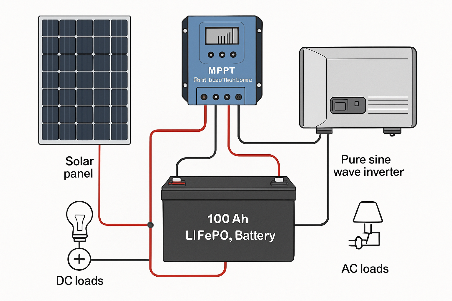
A home battery storage system diagram is the foundational blueprint for a safe, efficient, and long-lasting energy solution. More than just a sketch, it's a technical document that dictates how every component interacts. However, subtle errors in this diagram can lead to significant problems, including reduced performance, equipment damage, and serious safety hazards. Identifying these potential issues before installation is critical for any homeowner aiming for energy independence.
Flaw 1: Incorrect or Missing Overcurrent Protection
One of the most severe flaws in any electrical diagram is the improper implementation of overcurrent protection. These devices are the primary safety mechanism against electrical faults.
The Role of Fuses and Circuit Breakers
Overcurrent protection devices, like fuses and circuit breakers, are designed to interrupt the flow of electricity when the current exceeds a safe level. This prevents wires from overheating, which can melt insulation and cause fires. They protect against two main dangers: short circuits, which are sudden high-current surges, and overloads, where appliances draw more power than the system can safely provide. Think of them as a mandatory seatbelt for your electrical system; they are there to prevent catastrophic failure.
Common Diagram Mistakes
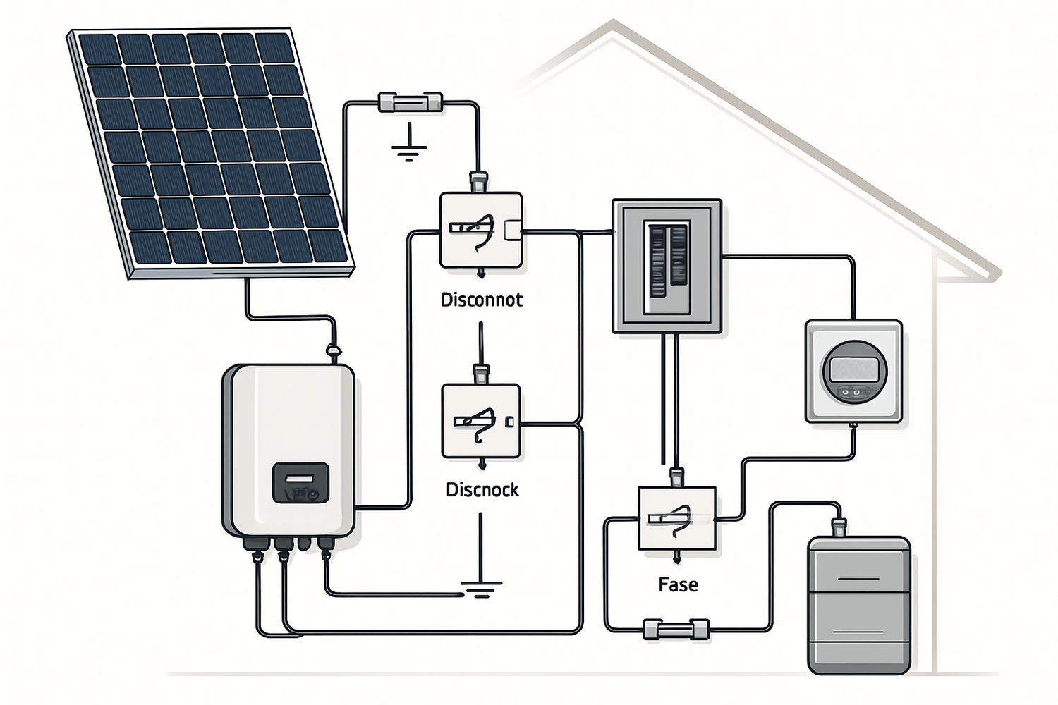
Diagrams often show these devices in the wrong location, with incorrect amperage ratings, or omit them entirely. For a home battery storage system, overcurrent protection is essential between the battery and the inverter, the solar panels and the charge controller, and between the inverter and the main electrical panel. A diagram that misses these components is fundamentally unsafe. According to research available from the U.S. Department of Energy, proper guidelines must be followed for system design and installation to ensure safety and reliability. As noted in the EERE Success Story—Empire State Strikes Back, resilient solar and storage systems are crucial for providing power during outages, and their correct implementation is paramount.
Flaw 2: Improper Wire Sizing and Voltage Drop
The lines drawn on a diagram represent physical wires, and their specified size, or gauge, is not arbitrary. Incorrect wire sizing directly impacts both safety and system efficiency.
Why Wire Gauge Matters
Properly sizing conductors is a critical step that directly impacts safety, performance, and long-term return on investment. Wires that are too small for the current they carry will overheat, creating a fire hazard. Additionally, all wires have some natural resistance, which causes a reduction in voltage, known as voltage drop. If the wires are undersized, this voltage drop becomes excessive, leading to significant power loss. This means less of the energy generated by your solar panels reaches your batteries or appliances, reducing the overall efficiency of your system. The National Electrical Code (NEC) generally recommends keeping voltage drop below 3% for this reason.
Identifying Sizing Errors in a Diagram
A detailed diagram should specify the wire gauge (e.g., AWG in North America) for each connection. A flaw exists if the specified gauge is insufficient for the maximum current of that circuit and its length. For example, a long run from the solar panels to the inverter requires a thicker wire to minimize voltage drop. A diagram that doesn't specify wire sizes at all is incomplete and should be considered a major red flag. For more details on how wiring affects system output, you can review this ultimate reference on solar storage performance, which explains key metrics.
Flaw 3: Neglecting Essential Disconnect Switches
Disconnect switches are crucial for safety and maintenance, allowing sections of the system to be de-energized manually. Their omission from a diagram is a serious oversight.
Safety and Maintenance
Disconnects allow an installer, maintenance professional, or emergency responder to safely isolate components like the inverter or battery. Without them, performing service or responding to an emergency would be extremely dangerous. The NEC has specific requirements for the location and type of disconnects in an energy storage system (ESS), often requiring a readily accessible disconnect outside the home for first responders.
Where Disconnects Are Commonly Missed
A proper home battery storage system diagram should show disconnects in several key locations. These include a DC disconnect between the solar array and the inverter/charge controller, a disconnect between the battery and the inverter, and an AC disconnect between the inverter and the main electrical panel. A diagram that lacks these access points fails to meet safety standards and makes future maintenance hazardous.
Flaw 4: Poor Grounding and Bonding Configuration
Grounding is a critical safety feature that protects both people and equipment from electrical faults and lightning. A flawed grounding plan can render a system unsafe.
The Purpose of System Grounding
A grounding system provides a safe path for fault currents to flow to the earth. This protects individuals from electric shock by preventing the metal casings of equipment from becoming energized. It is essential for protecting against lightning strikes and other electrical surges. For battery energy storage systems, robust and carefully designed grounding systems are necessary to prevent issues like thermal runaway and ensure a long service life.
Diagrammatic Signs of Improper Grounding
An incorrect diagram might show a 'floating' ground that isn't connected to a proper earth ground (like a ground rod), or it may lack bonding between all metallic components. All non-current-carrying metal parts, including solar panel frames, mounting racks, and inverter and battery enclosures, must be bonded together and connected to the grounding system. A diagram that fails to show a clear, continuous path to a verified earth ground is a sign of a flawed and dangerous design.
Flaw 5: Inadequate Battery Management System (BMS) Integration
Modern lithium-ion batteries, including Lithium Iron Phosphate (LiFePO4) types, rely on a Battery Management System (BMS) for safe and efficient operation. A diagram must reflect its central role.
The Brain of the Battery
The BMS is an electronic system that monitors and manages the battery pack. Its primary functions are to protect the battery from over-charging, over-discharging, and operating in extreme temperatures. It also ensures the health of the battery by balancing the charge across all the individual cells. According to the International Energy Agency's report on Clean Energy Innovation, advancements in battery applications are a key part of the future energy landscape, and the BMS is central to this technology.
How Diagrams Fail to Represent the BMS
A common flaw is treating the battery as a simple two-terminal box. A correct diagram for a smart lithium battery will show the communication wiring between the BMS and the inverter. This communication allows the inverter to adjust charging and discharging based on the battery's status, which is crucial for both performance and longevity. Without this integration, the system cannot operate optimally, and the battery is at a higher risk of damage.
A Final Look at Your System's Blueprint
A home battery storage system diagram is far more than a simple drawing; it is a critical document that dictates the safety, efficiency, and reliability of your entire energy system. The five flaws discussed—missing overcurrent protection, improper wire sizing, absent disconnects, poor grounding, and inadequate BMS integration—can turn a promising investment into a liability. Always ensure your diagram is comprehensive, compliant with local codes, and reviewed by a qualified professional before any installation work begins. This diligence is the first and most important step toward achieving true energy independence.
Disclaimer: This article is for informational purposes only and does not constitute professional electrical or financial advice. Always consult with a certified electrician and relevant professionals before designing or installing a solar energy storage system.
Frequently Asked Questions
What is the most common error in a solar energy storage diagram?
Missing or incorrectly sized overcurrent protection is one of the most frequent and dangerous errors. Fuses and circuit breakers are non-negotiable safety components, and their proper placement and rating are critical to prevent fire and equipment damage.
Can I design my own home battery storage system diagram?
While it is possible for individuals with extensive knowledge of electrical engineering and local codes, it is not recommended for most. A flawed diagram can lead to safety hazards and costly mistakes. It is always best to have your diagram created or at least reviewed by a certified professional.
How does a diagram affect my system's performance?
A diagram directly impacts performance through specifications like wire sizing. Undersized wires lead to voltage drop, which reduces the amount of power delivered from your panels to your batteries and from your batteries to your home, lowering overall system efficiency. Proper BMS integration shown in the diagram is also key to optimizing battery life and performance.


Leave a comment
All comments are moderated before being published.
This site is protected by hCaptcha and the hCaptcha Privacy Policy and Terms of Service apply.