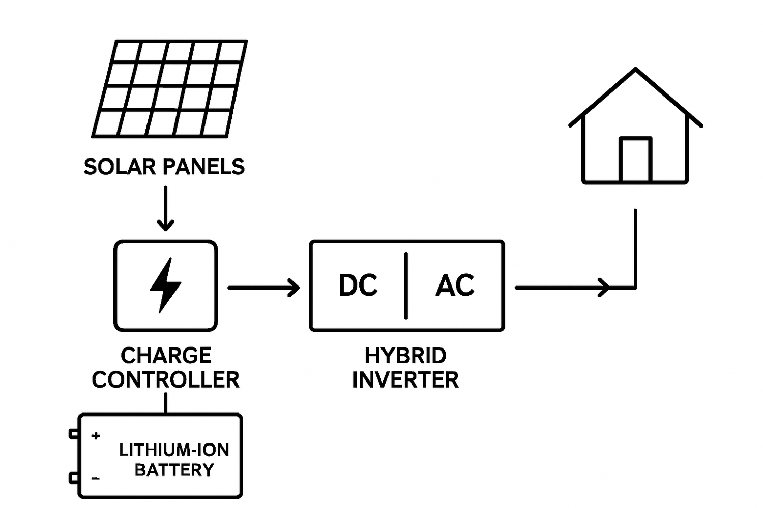
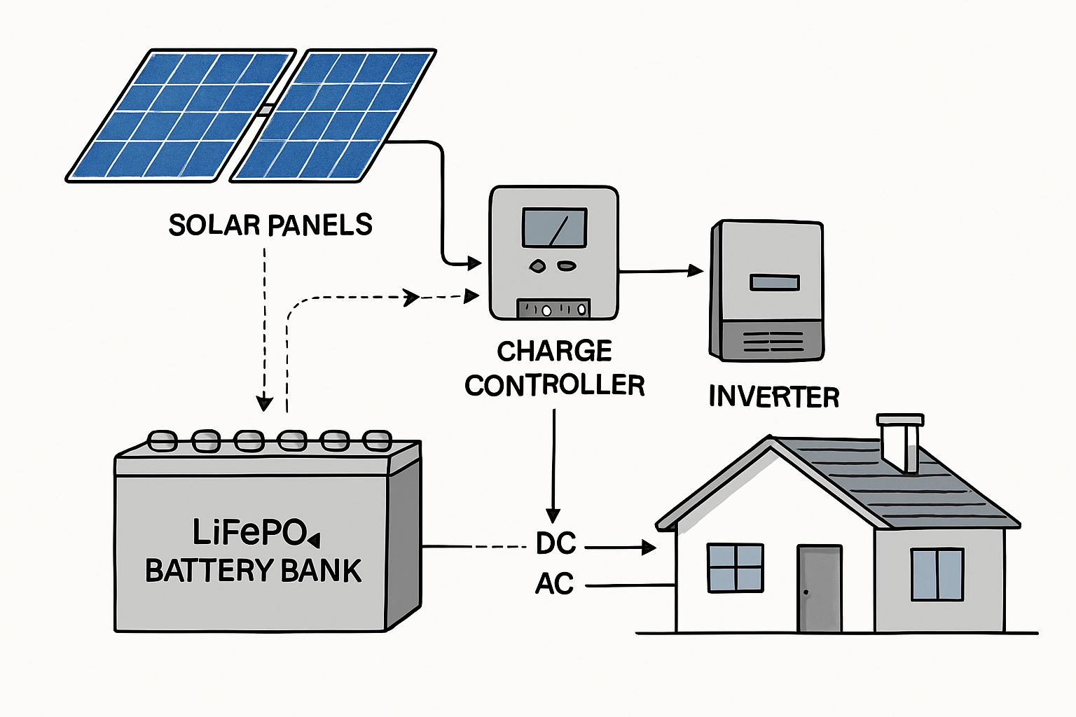
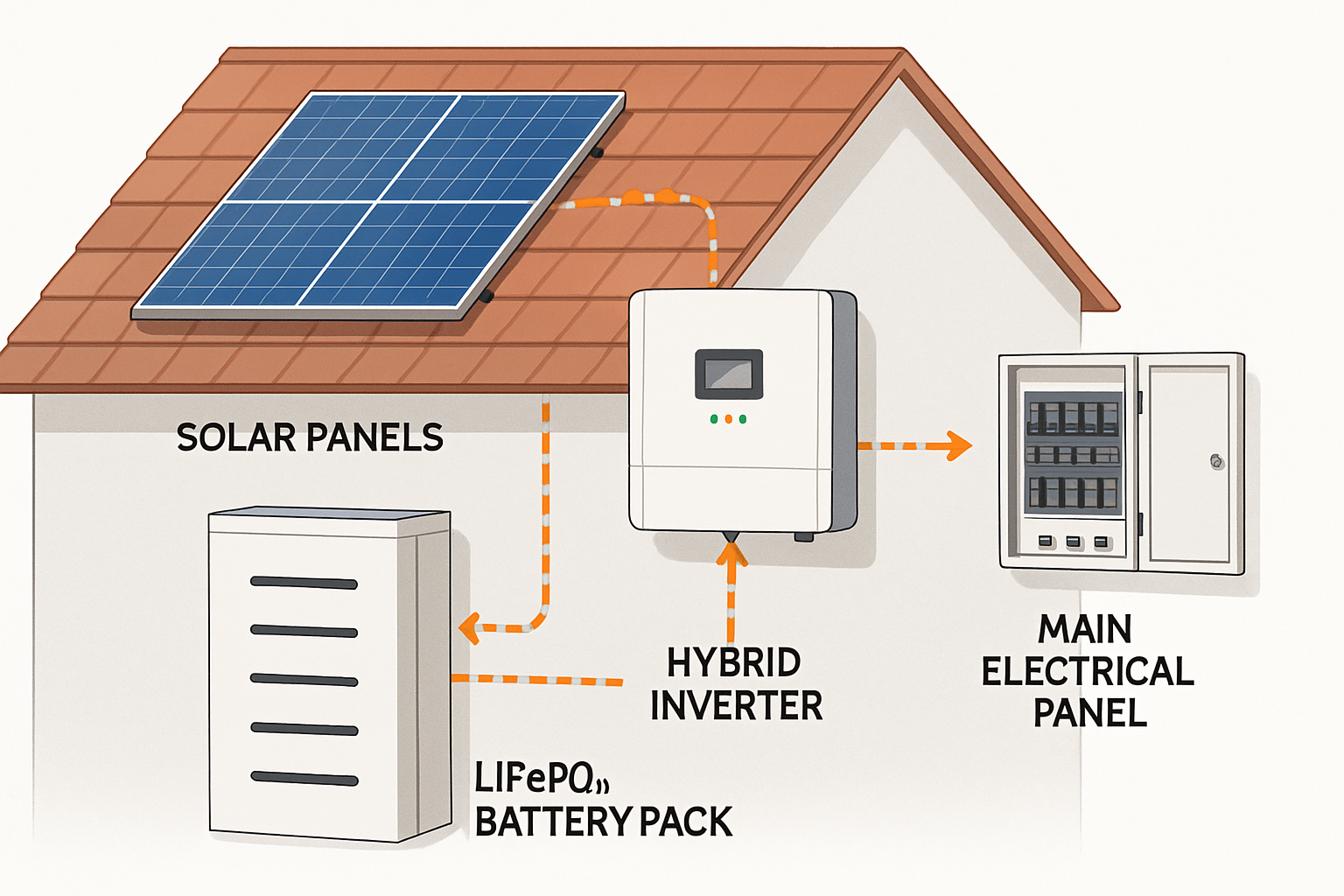
A solar energy storage system is a carefully orchestrated assembly of technology. While the solar panels on the roof are the most visible part, the true operational blueprint is the Li-Ion solar battery diagram. This schematic is more than just a technical drawing; it is a complete map of your energy independence. It details how every component connects, how power flows, and how the system ensures safe, reliable operation. Understanding this diagram empowers you to have meaningful conversations with installers and to fully grasp your system’s capabilities.
The Core Components of a Lithium-Ion Solar Battery System
Every solar energy storage system diagram illustrates a collection of essential devices working in concert. Recognizing these core components is the first step in decoding the overall schematic. Each symbol represents a piece of hardware with a specific and critical function.
The Energy Source: Solar Panels (PV Array)
The journey of solar energy begins at the photovoltaic (PV) array. These panels are responsible for converting sunlight directly into direct current (DC) electricity. On a diagram, they are typically shown as a series of connected rectangles. The schematic will often specify the total wattage of the array, giving you a clear idea of the system's power generation capacity.
The Brains of the Operation: The Inverter
The inverter is a central component that manages power flow. According to the Solar Energy Perspectives report, an inverter's primary role is to transform the DC electricity from the panels and battery into alternating current (AC) electricity, which is the standard form of power used by household appliances. A diagram will distinguish between different inverter types, such as hybrid inverters that can manage inputs from solar panels, batteries, and the grid simultaneously.
The Heart of the System: The Lithium-Ion Battery
The lithium-ion battery, particularly the Lithium Iron Phosphate (LiFePO4) variety, is the reservoir for your solar energy. It stores excess power generated during the day for use at night or during outages. The diagram will show the battery's connection to the system and usually note its voltage and capacity in Amp-hours (Ah) or kilowatt-hours (kWh). As the International Renewable Energy Agency notes in its Renewable Power Generation Costs in 2024 report, battery deployment is expanding significantly to support modern power systems.
The Gatekeeper: The Solar Charge Controller
Between the solar panels and the battery lies the charge controller. This device acts as a gatekeeper, regulating the voltage and current from the PV array to prevent the battery from overcharging. This function is vital for protecting the battery's health and extending its lifespan. A diagram will show its position in the DC circuit, ensuring the battery receives a stable and safe charge.
Decoding the Language of the Diagram: Symbols and Connections
A solar power diagram interpretation relies on understanding its visual language. This includes the lines that represent wires, the symbols for safety devices, and the arrows that indicate the direction of energy flow. Mastering these elements allows you to trace the path of electricity through the system.
Understanding Lines and Wires
Lines on the diagram represent the physical wires that connect each component. They are often color-coded or labeled to distinguish between DC and AC circuits. The diagram may also specify the wire gauge (thickness), which is critical for safety and efficiency. Undersized wires can overheat and cause power loss, so a proper schematic ensures the correct wiring is used for the expected electrical load.
Essential Safety Components
A well-designed diagram will prominently feature safety devices. Fuses and circuit breakers are included to protect against overcurrent events, immediately cutting power if a fault is detected. Disconnect switches are also shown, which allow for the safe isolation of components like the inverter or battery for maintenance. Proper grounding, indicated by a specific symbol, is another non-negotiable safety feature that protects against electrical shocks.
What the Diagram Tells You About System Performance and Reliability
Beyond component identification, a Li-Ion solar battery diagram reveals deeper insights into the system's performance, efficiency, and future-readiness. It shows not just what the system is, but how well it can perform its job.
System Sizing and Capacity
The specifications listed on the diagram—such as panel wattage, battery kWh, and inverter kW—tell you if the system is properly sized for your energy needs. An undersized system will fail to meet your demands, while an oversized one may be an unnecessary expense. The diagram provides a clear, at-a-glance summary of the system's power and storage capabilities.
Efficiency and Coupling: AC vs. DC Systems
The schematic will show whether the system is 'AC-coupled' or 'DC-coupled'. This refers to how the battery connects to the system. As explained in an EERE Success Story, DC-coupled systems can be more efficient because they require only one inverter for both solar harvesting and battery management. This configuration minimizes the number of times power is converted between DC and AC, reducing energy loss.
| Feature | DC-Coupled System | AC-Coupled System |
|---|---|---|
| Inverter Count | One hybrid inverter | Two inverters (one for solar, one for battery) |
| Efficiency | Generally higher due to fewer power conversions | Slightly lower due to multiple DC-AC-DC conversions |
| Best Use Case | New solar and storage installations | Adding battery storage to an existing solar PV system |
Scalability and Future-Proofing
A thoughtfully designed diagram may also indicate pathways for future expansion. It might show available space on an inverter for an additional string of solar panels or a setup that allows for the easy addition of more battery modules. This foresight in the design phase ensures your energy solution can grow with your needs, making it a scalable and long-term investment.
A Final Look at Your System's Blueprint
A Li-Ion solar battery diagram is far more than a collection of lines and symbols. It is the definitive guide to your solar energy storage system. It outlines the system's architecture, its safety mechanisms, and its operational logic. By learning to read this blueprint, you gain a deeper understanding of how your system generates, stores, and delivers clean energy. This knowledge is invaluable for ensuring your system is installed correctly, operates efficiently, and provides reliable power for years to come. To truly evaluate a system's long-term value, it helps to analyze key performance indicators. For a deeper look, consider exploring the ultimate reference on solar storage performance, which details metrics like depth of discharge and cycle life.
Frequently Asked Questions
Why is a solar battery diagram so important?
It is a crucial tool for design, installation, and troubleshooting. It ensures all components are correctly integrated for safety and optimal performance, serving as a common reference for installers, owners, and technicians.
What's the biggest mistake to avoid when reading a schematic?
Ignoring the safety components like fuses, breakers, and proper grounding. These elements are non-negotiable for protecting your investment, your property, and ensuring the system operates safely under all conditions.
Can I design my own solar energy storage system diagram?
While it is possible with sufficient knowledge, creating a safe and compliant diagram requires a deep understanding of electrical principles and local electrical codes. It is highly recommended to consult with a qualified professional to ensure the design is sound and secure.
What does 'DC-coupled' versus 'AC-coupled' mean on a diagram?
It describes how the solar panels and battery are connected. In a DC-coupled system, solar DC power flows to the battery through a charge controller before being inverted to AC for use. In an AC-coupled system, solar DC power is first inverted to AC, and then a separate battery inverter converts it back to DC to charge the battery.


Leave a comment
All comments are moderated before being published.
This site is protected by hCaptcha and the hCaptcha Privacy Policy and Terms of Service apply.