Achieving energy independence is a powerful goal. It means having control over your power supply, reducing reliance on the grid, and gaining resilience against outages. The foundational blueprint for this goal is the solar system diagram. This schematic is more than just a technical drawing; it is the strategic map that guides the design, installation, and maintenance of a robust solar energy storage system. Understanding this diagram empowers you to build a solution tailored to your exact needs.
The Anatomy of a Solar Power System Diagram
A solar system diagram illustrates how individual components connect and interact to create a functional power system. Each part has a specific role, and their synergy is what enables you to generate, store, and use your own clean energy.
Core Power System Components
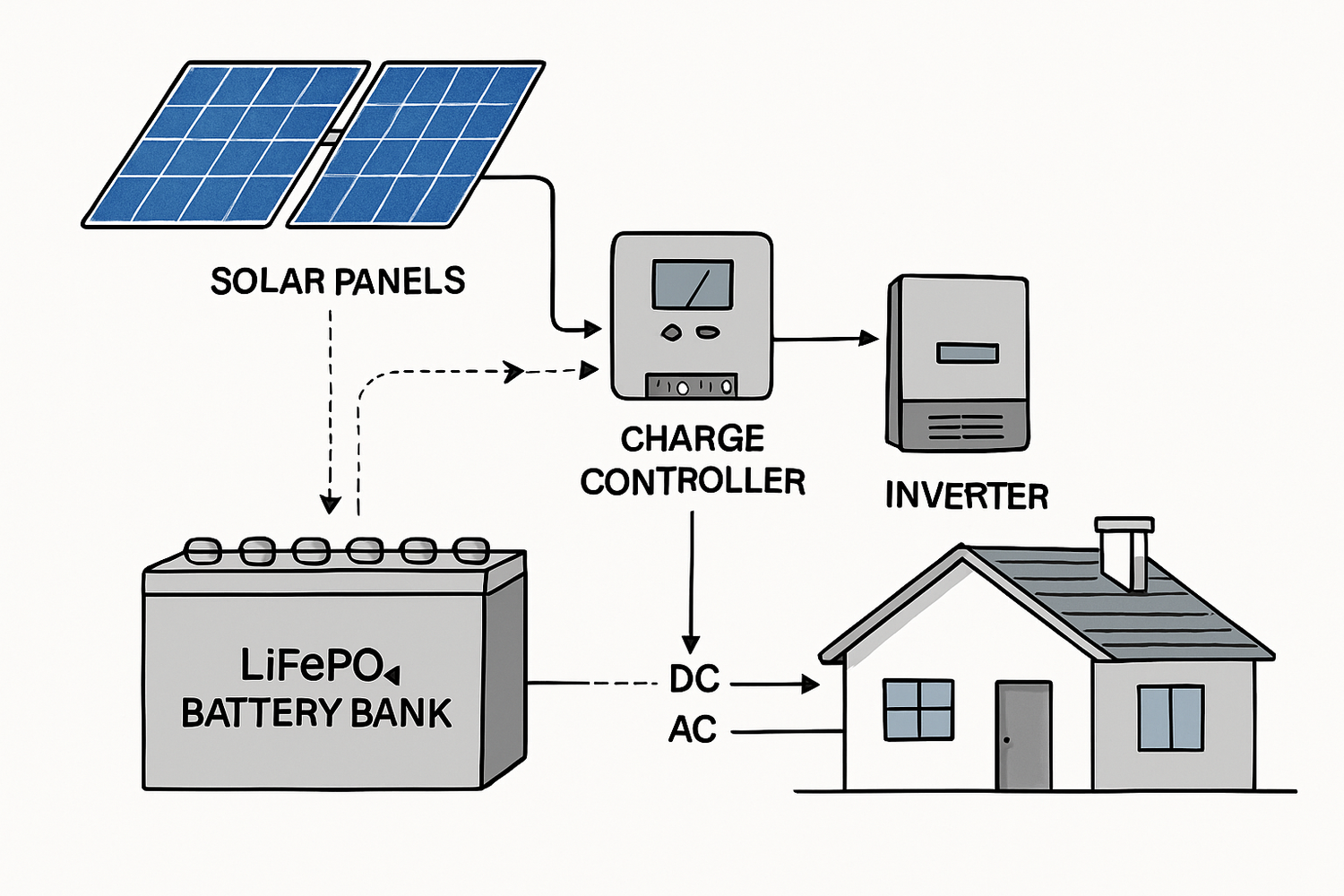
At its heart, a solar energy system consists of four primary components, each represented in the diagram:
- Solar Panels (PV Array): These are the energy collectors. They capture sunlight and convert it into Direct Current (DC) electricity. The diagram will specify the number of panels and how they are wired together (in series or parallel) to achieve the desired voltage and current.
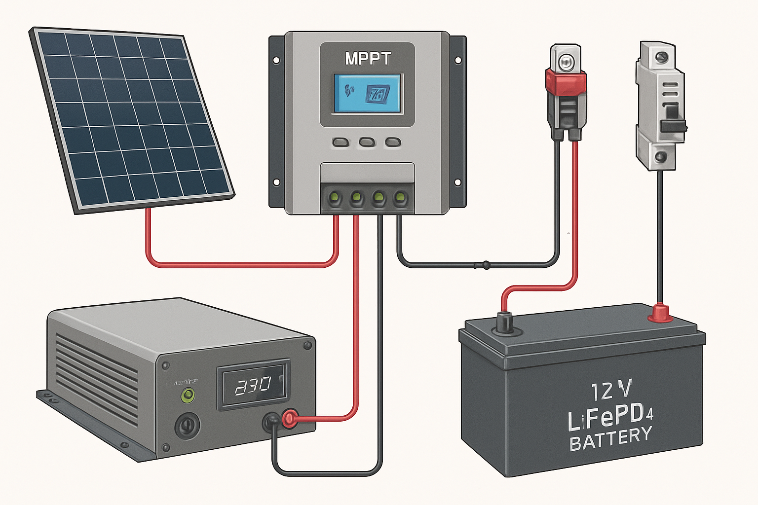
- Charge Controller: This device acts as the gatekeeper for your batteries. Its main function is to regulate the voltage and current coming from the solar panels to prevent the batteries from overcharging, which extends their lifespan and ensures safety.
- Battery Bank: This is the core of energy independence. High-performance lithium iron phosphate (LiFePO4) batteries store the DC energy generated by the panels. This stored energy is then available for use during the night, on cloudy days, or during a power outage.
- Inverter: The inverter is the system's translator. It converts the DC power from the batteries into Alternating Current (AC) power, which is the type of electricity used by most standard home appliances.
The Flow of Energy
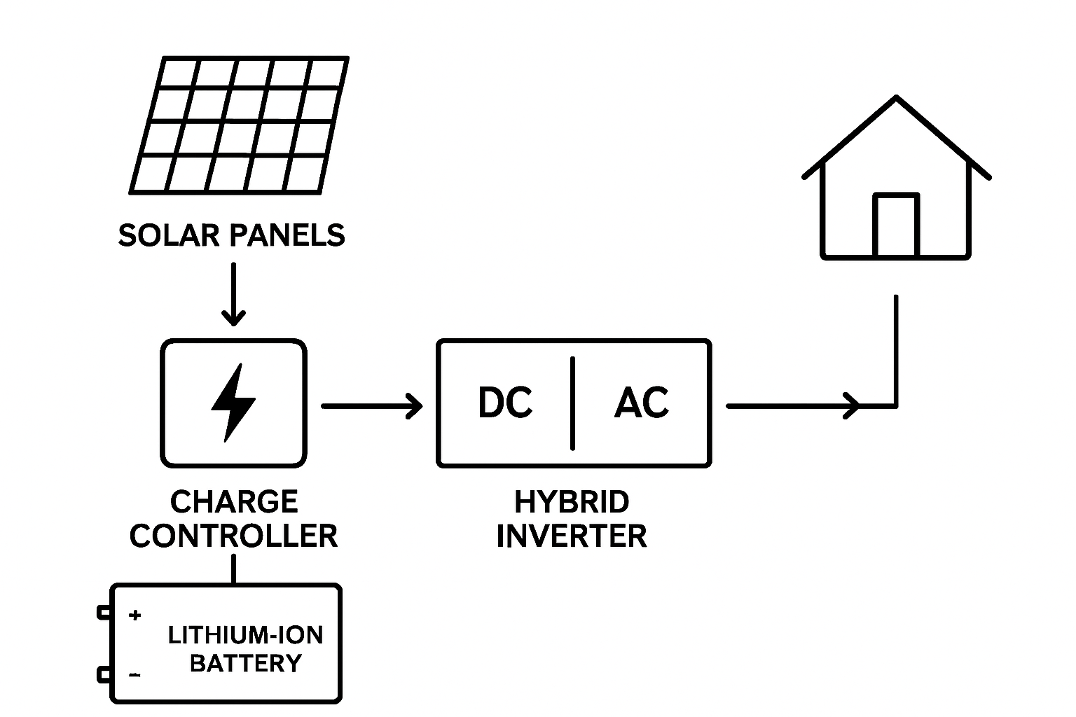
The diagram visually traces the path of electricity. Sunlight hits the solar panels, creating DC power. This power flows to the charge controller, which safely charges the battery bank. When you need power, the batteries release DC energy to the inverter. The inverter converts it to AC power, which is then sent to your home's electrical panel to run your lights, refrigerator, and other appliances. This seamless flow ensures you have power whenever you need it.
Designing for True Energy Independence
A generic diagram is a starting point, but a system designed for independence must be meticulously planned. It requires a deep dive into your specific energy consumption and goals.
Sizing Your System Correctly
The first step is a thorough load analysis to calculate your daily energy consumption in watt-hours. This involves listing all the appliances you intend to power and their daily usage. This data informs the size of your PV array, the capacity of your battery bank (e.g., a 12v 100ah lithium ion battery or a larger 48V system), and the power rating of your inverter. For off-grid systems, you should also plan for 'days of autonomy'—the number of consecutive cloudy days your system can sustain power without any solar input.
On-Grid, Off-Grid, and Hybrid Schematics
Solar system diagrams vary based on the type of system:
- Off-Grid: This diagram shows a completely self-contained system with no connection to the utility. The battery bank is absolutely critical.
- Grid-Tied: This system is connected to the utility grid but often lacks a battery. It allows you to reduce your electricity bill but does not provide backup power during an outage.
- Hybrid: A hybrid system diagram combines the best of both worlds. It is connected to the grid but also includes a battery bank. This allows you to store excess solar energy for use during peak-rate hours or grid failures, offering both savings and security.
Key Safety and Efficiency Elements in the Diagram
A professional solar system diagram prioritizes safety and efficiency. It specifies not just the components but also the protective devices and wiring that ensure reliable, long-term operation.
Fuses, Breakers, and Disconnects
These safety devices are non-negotiable. The diagram will indicate the precise locations for overcurrent protection, such as fuses or circuit breakers. They are placed between the panels and charge controller, the controller and batteries, and the battery bank and inverter. A main DC disconnect is also crucial for isolating the system for maintenance. According to the U.S. Department of Energy's work on microgrids, building resilient and safe energy systems is a key factor in supporting energy independence.
Wire Sizing and Performance
The lines connecting components in the diagram represent wires, and their size (gauge) is critical. Undersized wires can cause voltage drop, reducing efficiency and creating a potential fire hazard. The diagram informs the selection of appropriate wire gauges based on current and distance to minimize energy loss. Understanding the performance metrics of all components is crucial. For instance, data on battery efficiency and cycle life, as detailed in this ultimate reference on solar storage performance, directly impacts your system's long-term viability and return on investment.
Component Quality and Longevity
The diagram is a plan, but the quality of the components brings it to life. Choosing high-performance parts, like LiFePO4 batteries known for their long cycle life and safety, ensures the system you build is durable. As highlighted in the International Energy Agency's Solar Energy Perspectives report, advancements in solar technology have made it more accessible and reliable for residential applications.
From Blueprint to Reality: Practical Applications
A well-designed diagram is the first step toward real-world energy solutions. It can be adapted for various scenarios, from small cabins to large residential homes.
Residential Off-Grid Power
For a remote home or cabin, the solar diagram is the complete electrical blueprint. It would typically feature a large PV array, a high-capacity battery bank (often a 48V LiFePO4 configuration for efficiency), and a powerful pure sine wave inverter capable of running sensitive electronics and large appliances simultaneously.
Battery Backup for Grid-Tied Homes
For homeowners who want to add resilience to their existing grid-tied system, a hybrid diagram provides the roadmap. It shows how to integrate a battery bank, a hybrid inverter, and a critical load sub-panel. This setup ensures that essential appliances like refrigerators, lights, and medical devices remain powered during a grid outage.
Component Performance Comparison
The choice of battery technology is one of the most significant decisions in designing a system for energy independence. The table below compares the two most common options.
| Feature | Lithium Iron Phosphate (LiFePO4) | Sealed Lead-Acid (AGM) |
|---|---|---|
| Average Lifespan (Cycles) | 4,000 - 10,000+ cycles | 300 - 1,000 cycles |
| Usable Capacity (Depth of Discharge) | 80% - 100% | 50% |
| Round-Trip Efficiency | 95%+ | ~80-85% |
| Maintenance | None | None |
| Upfront Cost | Higher | Lower |
Your Diagram, Your Energy Future
Your solar system diagram is far more than a technical requirement. It is a personalized plan for achieving energy freedom. By understanding its components, the flow of energy, and the critical safety features it outlines, you are equipped to build a safe, efficient, and reliable solar energy storage system. This blueprint is the key to taking control of your power and securing your energy future, independent of external uncertainties.
Frequently Asked Questions
What is the most critical component in a solar diagram for energy independence?
The battery energy storage system is the most critical component for true energy independence. While solar panels generate power, the battery bank stores it for use at night or on cloudy days, ensuring a continuous power supply.
Can I use a standard solar diagram for any house?
No. A solar system diagram should be customized to your specific energy needs, geographic location (sunlight hours), and desired level of autonomy. A one-size-fits-all approach can lead to undersized systems that fail to meet your requirements or oversized systems that are not cost-effective.
How does an inverter work in a solar power system?
An inverter converts the Direct Current (DC) electricity generated by your solar panels and stored in your batteries into Alternating Current (AC) electricity. AC power is the standard used by most household appliances, making the inverter an essential bridge between your solar system and your daily energy use.


Leave a comment
All comments are moderated before being published.
This site is protected by hCaptcha and the hCaptcha Privacy Policy and Terms of Service apply.