In my line of work, the conversation around solar has shifted. It's no longer just about generating kilowatts; it's about actively supporting the grid. The single most critical piece of that puzzle is the inverter's ability to handle a grid fault—what we call Fault Ride-Through (FRT). The days of inverters simply disconnecting during a voltage dip are long gone. Today, they have to stay online and help fix the problem. The key to achieving this without massive energy loss lies in the inverter's core design: its topology and the components within it.
How Grid Rules Forced Inverters to Get Smarter
I remember when early grid codes basically told solar plants to run for the hills at the first sign of trouble. As IRENA's reports like Grid Codes for Renewable Powered Systems show, this became a huge liability. A minor grid event could cause a cascade of solar plants to trip offline, creating a much bigger blackout. We saw the rules change firsthand, mandating that inverters must "ride through" both low-voltage (LVRT) and high-voltage (HVRT) events, actively supporting the grid instead of abandoning it.
The Inverter Topologies I Work With for FRT
An inverter's topology is its fundamental electrical blueprint, and it directly dictates how well it can handle the stress of a fault.

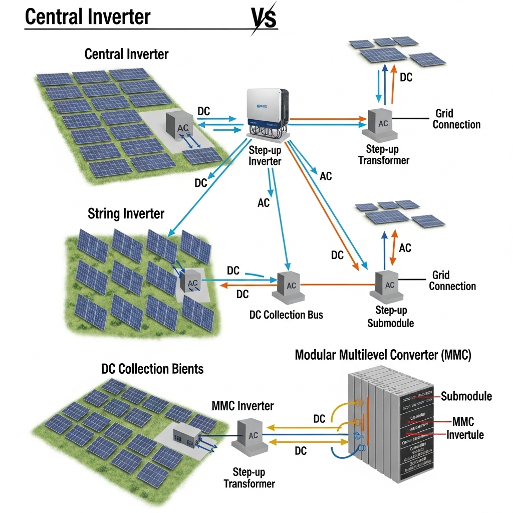
The Workhorses: Central and String Inverters
For years, utility-scale projects have relied on massive **central inverters**. They are cost-effective but can be slow to react with the granular control we need today. **String inverters** brought a more modular approach, which naturally provides better fault isolation. Both have been updated with advanced digital controls to meet modern FRT requirements, but the real game-changers are the more advanced topologies.
The Premier League: MMC and CHB Topologies
For projects where grid stability is non-negotiable, we turn to designs like the **Modular Multilevel Converter (MMC)** and **Cascaded H-Bridge (CHB)**. Instead of one big power stage, they use dozens of smaller modules to build a near-perfect AC waveform. This gives us surgical control over voltage and current, allowing the inverter to provide services like synthetic inertia. As the IEA notes in its work on the System Integration of Renewables, this level of control is what's needed for a grid dominated by renewables.
Why the Right Switches Matter for Low-Loss Performance
Inside the inverter, semiconductor switches are doing the brutal work of chopping up DC current thousands of times a second. During a fault, they are under incredible stress, and their efficiency determines whether the inverter survives and how much energy is wasted.
The Battle: IGBTs vs. Silicon Carbide (SiC)
For years, **IGBTs** were the go-to switch. They're reliable and cost-effective. But for high-performance FRT, my preference is increasingly for **Silicon Carbide (SiC) MOSFETs**. The difference is stark.
| Parameter | IGBT (Silicon) | SiC MOSFET (Silicon Carbide) |
|---|---|---|
| Switching Speed | Slower | Dramatically Faster |
| Switching Losses | Higher (More Waste Heat) | Lower (Less Wasted Energy) |
| Operating Temperature | Lower Tolerance | Higher Tolerance |
| My Takeaway | The reliable standard for most jobs. | Essential for high-efficiency, fast-response systems. |
SiC's speed allows the inverter's control system to react almost instantly to a voltage sag, injecting reactive power precisely when the grid needs it most. This speed means less energy is wasted as heat, which reduces stress on the entire system.
A Holistic View: It's More Than Just the Inverter
From a system design perspective, achieving robust, low-loss FRT isn't just about the inverter in isolation. It's about how it works with the entire system.
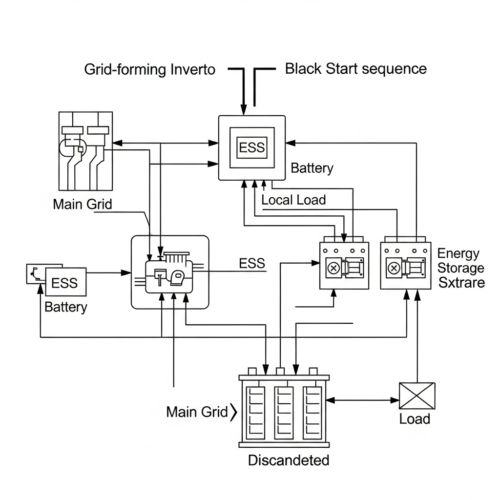
The Ultimate Stabilizer: Adding Energy Storage
Pairing a PV inverter with a battery is the single best way to enhance its FRT performance. A battery can absorb or inject huge amounts of power in milliseconds, acting as a buffer that gives the inverter incredible flexibility to manage the fault. This synergy dramatically reduces stress on the inverter's components and is becoming a standard design practice for critical projects.
The Engineer's Challenge: Balancing Performance and Cost
My job always comes down to balancing trade-offs. An MMC topology with SiC components is the gold standard for performance, but it comes at a premium. The final decision rests on a project's specific grid code requirements and financial model. The goal is always to select a design that not only meets today's compliance rules but will serve as a reliable, low-loss grid asset for the next 20 years.
Leave a comment
All comments are moderated before being published.
This site is protected by hCaptcha and the hCaptcha Privacy Policy and Terms of Service apply.