Roadmap: current sharing and phase lock in multi‑inverter stacks

Roadmap: current sharing and phase lock in multi‑inverter stacks

Scaling up a solar energy system often involves connecting multiple inverters. This technique, known as stacking or parallel operation, allows you to increase power output for large loads or create a 240V split-phase supply. The success of such a system hinges on two critical principles: precise current sharing and perfect phase lock. Without them, you risk equipment damage and system instability. This roadmap charts the course of these technologies, from their fundamental concepts to the advanced grid-forming capabilities shaping the future of microgrids.

The Foundation: Why Current Sharing is Non-Negotiable

Imagine a team trying to lift a heavy object. If one person doesn't pull their weight, others become strained, and the entire effort can fail. In a parallel inverter system, current sharing ensures every inverter carries its proportional share of the electrical load, preventing any single unit from being overworked.

Consequences of Imbalance

When current sharing fails, the consequences can be severe. One inverter may take on a disproportionate amount of the load, leading to overheating and thermal shutdown. Over time, this chronic stress can cause premature component failure. In more extreme cases, imbalanced loads can create circulating currents between the inverters—a wasteful and potentially damaging flow of energy that accomplishes no useful work and generates excess heat.

From Basic to Advanced Load Balancing

Early methods for load balancing relied on a concept called droop control. This technique intentionally allows the inverter's output voltage to 'droop' slightly as the load increases, encouraging other inverters to pick up a share of the work. While functional, it lacks precision. Modern systems employ sophisticated digital signal processors (DSPs) and high-speed communication links. This allows inverters in a stack to communicate in real-time, making micro-adjustments to ensure the load is shared with remarkable accuracy.

Achieving Synchronization: The Role of Phase Lock

Alternating current (AC) is not a steady flow; it's a sine wave that oscillates back and forth. For multiple inverters to work together, their individual sine waves must be perfectly synchronized. This alignment is called phase lock, and it's achieved using a technology known as a Phase-Locked Loop (PLL).

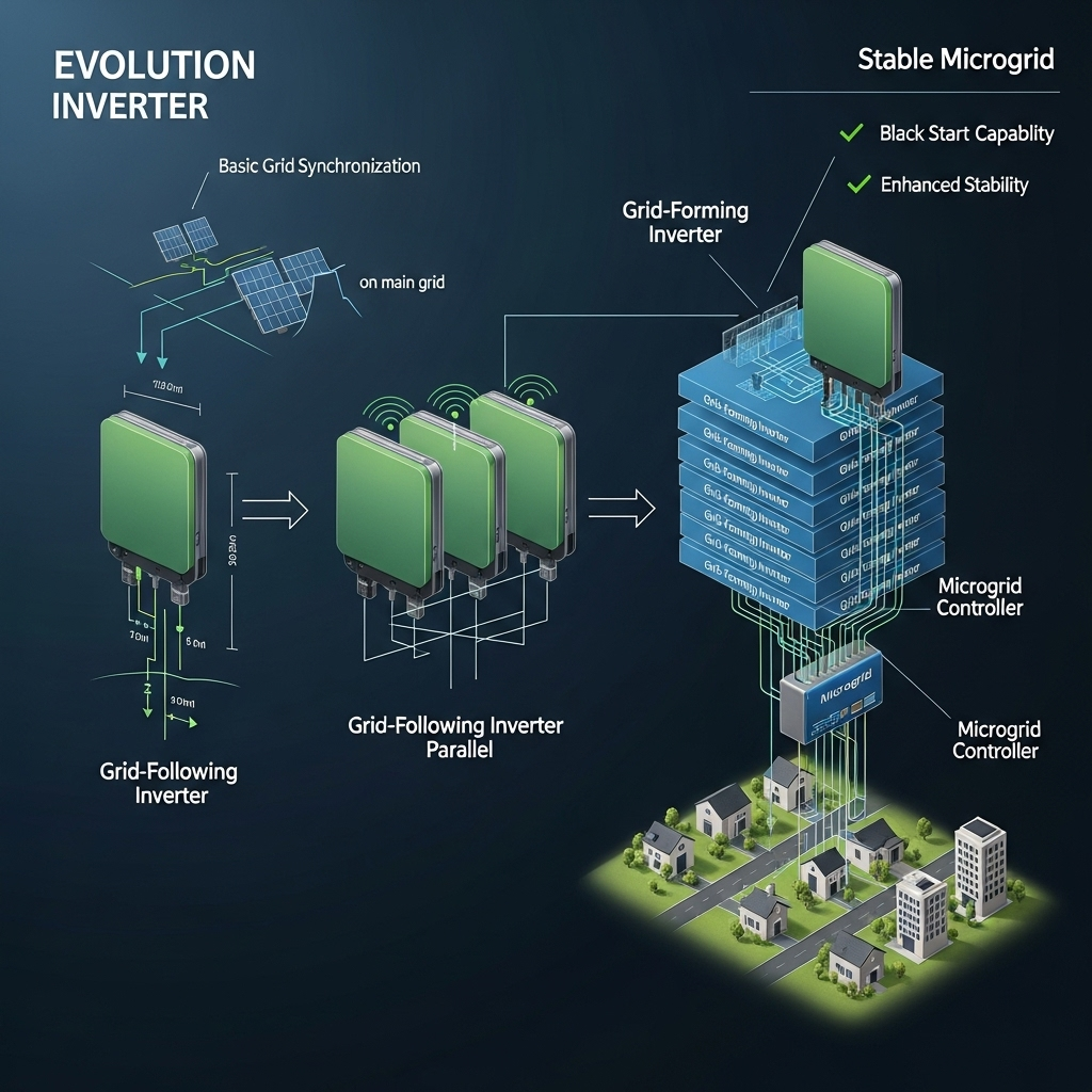
Evolution of inverter technology from grid-following to grid-forming stacks

Phase Lock in Parallel vs. Split-Phase Systems

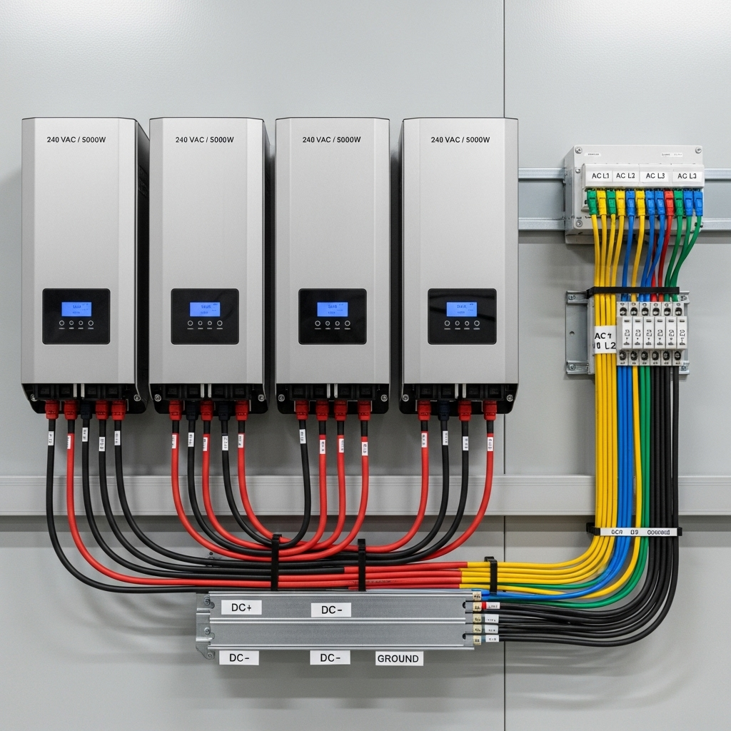
The goal of phase lock changes depending on the system configuration. In a parallel system, all inverters must produce sine waves that are perfectly in phase—peaking and crossing zero at the exact same moment. For a split-phase system designed to produce 120/240V power, the 'slave' inverter must maintain a sine wave that is precisely 180 degrees out of phase with the 'master' inverter. This opposition between the two phases creates the higher voltage needed for large appliances.

Key Differences in Stacked Configurations
Parameter Parallel Operation Split-Phase Operation
Primary Goal Increase current/power capacity at a single voltage (e.g., 120V) Create a dual-voltage supply (e.g., 120/240V)
Phase Relationship 0-degree phase shift (perfectly synchronized) 180-degree phase shift between master and slave
Output Wiring Outputs are tied together (L1 to L1, N to N) Outputs create two separate hot legs (L1 and L2) and a shared neutral
Common Use Case Powering many smaller loads or a single large 120V load Powering large appliances like well pumps, dryers, and EV chargers

The Roadmap: Evolving from Grid-Following to Grid-Forming

The intelligence that governs current sharing and phase lock is evolving rapidly. The industry is moving from inverters that simply follow an existing grid to inverters that can create a grid themselves. This shift is fundamental to building resilient and independent energy systems.

The Limitations of Grid-Following Inverters

Most traditional inverters are 'grid-following'. They use their internal PLL to detect the voltage and frequency of an external source—either the utility grid or a master inverter—and then synchronize their output to it. A study from the International Renewable Energy Agency, Grid Codes for Renewable Powered Systems, notes that these inverters cannot operate without an external voltage reference. This means a system composed entirely of grid-following units cannot start a microgrid from a blackout, a process known as a 'black start'.

The Rise of Grid-Forming Inverters

Grid-forming inverters are a significant leap forward. They are designed to operate without an external voltage reference, generating their own stable AC waveform to serve as the foundation for a microgrid. As the International Energy Agency points out in its Integrating Solar and Wind report, this capability is already being deployed in large-scale battery projects to enhance grid stability. When stacked, these inverters can work together to black-start an entire property, providing true energy resilience.

Future Outlook: Smart Stacks and Virtual Inertia

The most advanced multi-inverter systems operate as a single, intelligent unit. A stack of grid-forming inverters can provide what is known as 'virtual inertia'. They can respond instantaneously to changes in load or supply, inherently stabilizing the local grid much like the massive spinning generators in a traditional power plant. This capability is critical for operating a reliable power system with a high percentage of renewable energy sources. The development of new grid codes to accommodate these features is underway, paving the path for wider adoption.

Practical Implementation and Key Parameters

Achieving a stable multi-inverter stack requires careful attention to both hardware and software. The physical layout is just as important as the digital configuration.

Critical Hardware Considerations

Consistency is key. Always use identical inverter models with matching firmware versions. Mixing models can lead to communication conflicts and unpredictable behavior. Equally important is the wiring. All DC and AC cables connecting the inverters should be identical in length and gauge. This symmetry ensures equal resistance, preventing voltage drops that can disrupt a system's ability to share the load evenly.

Measuring and Verifying Performance

After installation, it is crucial to verify that the system is operating as expected. Using a clamp meter on the output of each inverter can confirm that they are sharing the load equally under various conditions. For a deeper analysis of overall system health, tracking key metrics is essential. You can find valuable information in this ultimate reference for solar storage performance, which covers how to monitor efficiency and state of charge effectively.

Looking Ahead: The Future of Inverter Stacking

The journey of multi-inverter technology is one of increasing intelligence and autonomy. What began as a method to simply increase power has evolved into the backbone of modern microgrids. Perfecting current sharing and phase lock remains the foundational requirement, but the future lies in grid-forming stacks that provide resilience, stability, and true energy independence. These advanced systems are transforming our ability to build robust, decentralized power networks for homes and businesses.

Frequently Asked Questions

What happens if phase lock is lost in a stacked system?

If phase lock is lost, the inverters will be outputting unsynchronized AC waveforms. This can cause large circulating currents, protective shutdowns, and potentially damage the inverters or connected appliances. Modern systems have built-in protections to shut down immediately if synchronization is lost.

Can you mix different inverter models in a parallel stack?

It is strongly discouraged. Different models may have different control algorithms, response times, and communication protocols, making it nearly impossible to achieve stable current sharing and reliable operation. Always use identical models from the same manufacturer for stacking.

How does cable length affect current sharing?

Cable length directly impacts resistance. If the cables connecting one inverter to the load are longer than the others, that path will have higher resistance. This causes a voltage drop, tricking the control system into thinking the load is smaller than it is and causing that inverter to underperform, which overloads the other units.

What is the main difference between grid-forming and grid-following inverters?

A grid-following inverter needs an existing grid (utility or another inverter) to synchronize with; it cannot create its own voltage source. A grid-forming inverter can generate its own stable AC waveform from a DC source (like a battery), effectively creating its own grid. This is essential for off-grid systems and microgrid black-start capabilities.

author avatar

Anern Expert Team

With 15 years of R&D and production in China, Anern adheres to "Quality Priority, Customer Supremacy," exporting products globally to over 180 countries. We boast a 5,000sqm standardized production line, over 30 R&D patents, and all products are CE, ROHS, TUV, FCC certified.

Reading next

Question: can you parallel dissimilar inverters safely long‑term?
8 mistakes that break load sharing in parallel inverter banks

Leave a comment

All comments are moderated before being published.

This site is protected by hCaptcha and the hCaptcha Privacy Policy and Terms of Service apply.