
Marine solar power frees boats from constant engine charging, yet myths persist. This piece separates facts from dock talk on boat solar panel output, solar shading in marine settings, and corrosion in salt air. You get practical numbers, physics in plain terms, and field-proven fixes.

Myth 1: “100 W makes 100 W all day on a boat”
Reality: Nameplate watts are measured in lab conditions. At sea, motion, heat, angle, and small shadows lower output. A better yardstick is daily watt‑hours per 100 W of panels, which ties to capacity factor.
Large datasets show fixed PV often runs in the mid‑teens capacity factor in many regions, shaping realistic daily yields. See EIA utility statistics and the value-focused PV discussion in Next Generation Wind and Solar Power by the IEA.
| Marine condition | Typical capacity factor | Daily energy per 100 W | Notes |
|---|---|---|---|
| Sunny subtropical, at anchor, arch‑mounted | 18–22% | 430–530 Wh | Clean panels, low shading |
| Temperate coast, mixed clouds | 12–18% | 290–430 Wh | Seasonal and weather swings |
| Underway with rigging shade | 7–12% | 170–290 Wh | Intermittent shadows cut peaks |
| Overcast or heavy haze | 3–8% | 70–190 Wh | Diffuse light, low irradiance |
| Deck‑mounted, little airflow | – | Subtract 5–15% | Heat penalty on flexible panels |
Panel orientation matters too. IEA notes that orientation and tilt change the production profile and annual yield; in high‑insolation areas, tracking can lift energy 12–25% for single‑axis and another 10–15% for dual‑axis systems, though added hardware and upkeep offset value on small craft (IEA, Next Generation). Boats rarely track, so placement and shade control do the heavy lifting.
Myth 2: “A small shadow barely matters on marine panels”
Reality: A thin shade line across cells can drop output sharply. PV modules group cells into substrings behind bypass diodes. Shade that covers a full row of cells along one edge can force a diode to conduct, shutting down that substring. The result is outsize loss from a small object like a boom, backstay, radar, or flag line.
How partial shading slices output
- Shade across the short side of a 36‑cell “12 V” module often disables roughly a third of the module area via one bypass diode.
- Edge shade that wanders can trigger different substrings across time, creating flicker in charging current and confusing some charge controllers.
- Patchy shade from rigging or antennas causes mismatch between parallel strings; the lowest‑performing section drags down the rest.
| Shade pattern | Typical impact | Mitigation |
|---|---|---|
| Thin boom shadow across full cell row | 30–60% module loss | Move panel aft/athwart; rotate panel orientation so shadows run along, not across, cells |
| Diagonal patch (antennas, radar) | 10–30% loss, fluctuating | Space panels apart; separate MPPTs |
| Mast or backstay sweeping on sail | Frequent clipping of peaks | Use multiple smaller panels across zones to “average” shade |
MPPT controllers help ride through changing irradiance. Real‑world testing shows better energy harvest versus PWM in variable shade and temperatures, a pattern aligned with the performance emphasis in IEA’s full report.
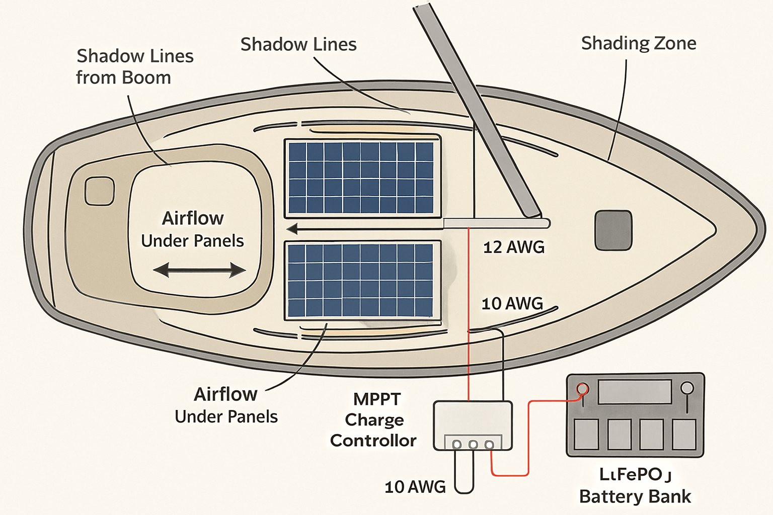
Layout tactics that work on boats
- Split the array. Two to four panels on separate MPPT inputs often beat a single large module under moving shade.
- Orient cells with the expected shadow direction. On arches, long dimension fore‑aft reduces cross‑cell shading from the boom.
- Keep walkable areas clear. Footprints abrade coatings and create microcracks that worsen mismatch over time.
Myth 3: “Marine panels are sealed; salt can’t hurt them”
Reality: Salt mist accelerates corrosion, wicks into crevices, and raises leakage currents. Frames, fasteners, terminals, and connectors suffer first. Module laminates are sealed, yet metal interfaces and cables still fight the sea.
Materials and assembly choices that survive
| Component | Better choice on boats | Why it lasts longer |
|---|---|---|
| Cable and lugs | Tinned copper, marine‑grade heat‑shrink with adhesive | Resists creep corrosion and wicking |
| Connectors | IP67/IP68 PV connectors, dielectric grease, firm click‑lock | Limits saline ingress; maintains contact resistance |
| Frames and mounts | Anodized aluminum isolated from 316 stainless with nylon washers | Reduces galvanic pairs and crevice attack |
| Sealants | Neutral‑cure marine sealant, UV stable | Prevents capillary salt paths |
| Bonding | Dedicated bonding straps and star washers | Controls fault currents; reduces pitting at random points |
Keep surfaces clean. Soiling cuts output, and the marine version of soiling is salt film. An Energy Department success story reports robotic cleaning can maintain output while using 75% less water than conventional methods for utility arrays (EERE Success Story—Drones Help Solar Site Design Take Flight). On boats, a freshwater rinse after passages and a soft brush restore clarity and limit corrosion seeds.
Inspection routine that actually prevents failures
- Quarterly: Open junction boxes and connectors for green or white deposits; clean and re‑terminate if needed.
- After heavy spray: Rinse panels, connectors, and cable runs. Check GFCI/RCD trips on inverters if fitted.
- Annually: Pull a fastener sample; look for crevice corrosion and galling. Re‑bed mounts that show leaks.
PV’s modular build enables tailored form factors for harsh sites, noted by the IEA in Solar Energy Perspectives. On small craft, that means prioritizing protective interfaces as much as the module itself.
Myth 4: “Decks and sea breeze keep panels cool”
Reality: Heat is a steady output killer. Most crystalline modules lose roughly 0.3–0.5% of power per °C above 25°C. Flexible panels bonded to decks run hot because there is no airflow under them. An air gap of 25–50 mm can drop cell temperature dramatically and lift daily yield.
- Expect 10–20% less energy from deck‑bonded flexible panels versus the same wattage on a ventilated arch in summer sun.
- White decks help a bit; shade gaps under the panel help more.
- Leave a slight tilt (5–10°) to aid self‑cleaning and rain runoff. IEA notes tilt shifts seasonal output, trading some summer energy for more winter energy in higher latitudes (IEA, Next Generation).
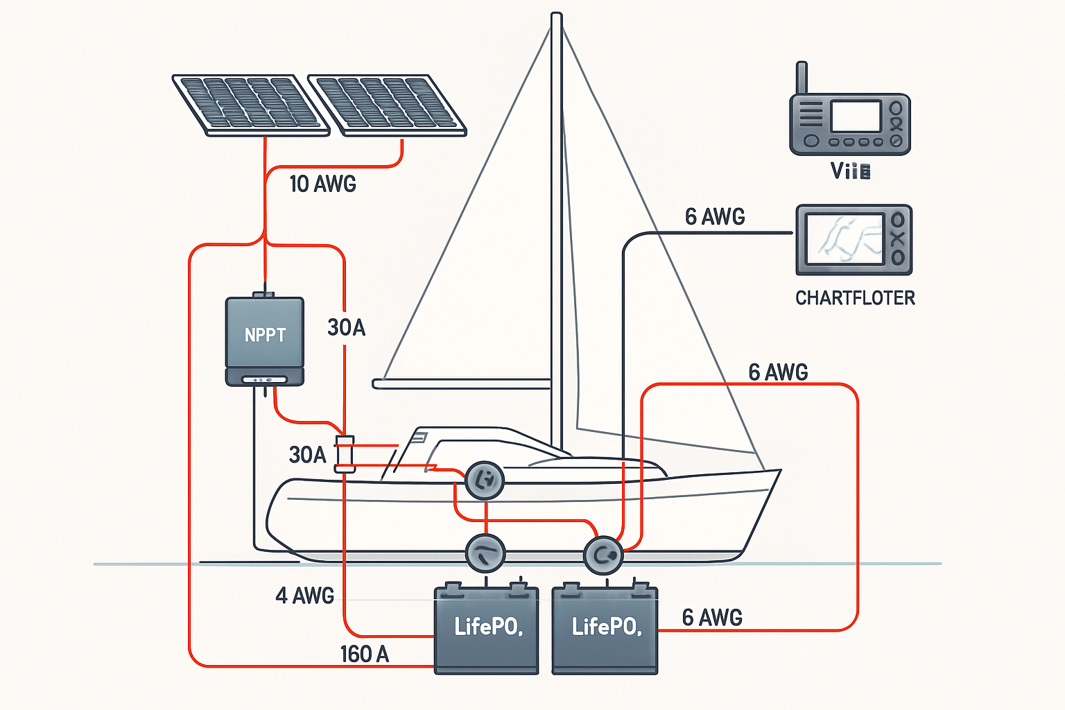
Myth 5: “Solar alone covers all onboard energy needs”
Reality: Marine solar can run lights, instruments, comms, pumps, and a fridge on many boats. High‑draw loads like air‑con and electric cooking usually need hybrid sources. A right‑sized LiFePO4 battery buffers variable sun and shade while cutting engine hours. That modular mix tracks industry trends toward flexible, storage‑supported PV highlighted by IRENA and IEA (IRENA, IEA).
Practical pairing tips
- Use MPPT with profiles suitable for LiFePO4 to capture rapid light swings and finish absorb correctly.
- Target cable voltage drop under 3% from panels to controller; use tinned copper and correct crimp tools.
- Fuse each parallel string near the combiner to avoid reverse‑feed in faults.
Quick myth busters
| Myth | Reality | Action |
|---|---|---|
| “Any shade is minor” | Edge shade can trip a bypass diode and kill a substring | Relocate panels, split inputs, align with shadow paths |
| “Panels are maintenance‑free” | Salt film and loose connectors sap watts | Rinse, inspect, re‑terminate, protect with grease |
| “Bigger panel beats two small ones” | One panel under shade underperforms two split panels | Use multiple modules on separate MPPTs |
| “Deck mounting is fine” | Heat hurts; airflow adds watts | Raise panels; leave a tilt and air gap |
Data notes and credible signals
- Orientation, tilt, and tracking shape both daily and annual PV yield; single‑axis tracking can add 12–25% in high sun regions (IEA).
- Cleaning and soiling control sustain output; automated methods have shown large maintenance gains in utility PV (Energy.gov EERE).
- PV’s modularity and application‑specific form factors enable robust marine solutions, per IEA Solar Energy Perspectives.
- Capacity‑factor thinking aligns boat expectations with land PV data from EIA.
Putting it all together at sea
Start with honest output ranges, design to avoid moving shade, ventilate panels, harden every connection, and let a lithium battery smooth the ride. That mix turns myths into manageable trade‑offs and raises uptime at anchor and underway.
FAQ
How much can a boom shadow cut boat solar panel output?
A thin shadow across a full row of cells can disable a bypass diode substring. Expect 30–60% loss on that module while the shadow sits there. Splitting arrays across two or more MPPT inputs reduces the hit.
Do tilt mounts help on a boat?
A small fixed tilt (5–10°) improves self‑cleaning and rain runoff and can lift winter yield at higher latitudes. Moving trackers add complexity and are rarely worth it on small craft, as noted by the IEA’s tracking tradeoff discussion.
How do I reduce marine solar corrosion?
Use tinned copper conductors, IP67/68 connectors with dielectric grease, isolate stainless from aluminum with nylon washers, and rinse salt film. Inspect and re‑terminate any discolored connectors.
Is MPPT worth it under variable shading?
Yes. MPPT reacts to fast changes in light and temperature and tends to harvest more energy than PWM on boats with intermittent shade and motion.
Can marine solar power a fridge reliably?
Often yes, if you pair a realistic array with a LiFePO4 bank sized to your daily amp‑hours and your anchoring pattern. The key is honest output math and shade‑smart layout.
Safety and non‑advice notice: This content is for information only and is not legal, engineering, or investment advice. Follow manufacturer instructions and marine electrical standards. Seek a qualified marine electrician for compliance and safety checks.
Leave a comment
All comments are moderated before being published.
This site is protected by hCaptcha and the hCaptcha Privacy Policy and Terms of Service apply.