Marine solar power excels at quietly running electronics, instruments, and a fridge. The MPPT charge controller is the part that decides how much of the panel’s watts actually reach your battery. On a moving boat with shade from rigging and variable sun angles, the right MPPT can add hours of usable energy each day. This piece shares tested controller archetypes, field data, and clear settings to raise yield without radio noise or overheated gear.

Why MPPT matters at sea
Pulse-width modulation (PWM) controllers are simple, but they throw away panel voltage above battery voltage. Maximum Power Point Tracking (MPPT) converts that extra voltage into current, which is critical on boats where shade and motion shift panel operating points minute by minute.
- Variable irradiance is the rule offshore. As noted in Integrating Solar and Wind by the IEA, fast changes in sun and wind demand responsive power electronics. On deck, boom swings and swells create similar short-term ramps that MPPT can follow to hold near the true power point.
- High module voltage helps in weak sun. Energy.gov explains that PV voltage is sensitive to temperature and light; MPPT harvests extra volts on cool mornings and converts them to usable amps for your 12 V or 24 V bank.
- Daily gain vs PWM. In mixed sun and partial shade on a 300 W array, MPPT commonly nets 10–25% more watt-hours than PWM. On flat morning/afternoon angles the gain is often on the high end.
Policy research underscores the value of smart power electronics. Grid reports such as the IEA’s System Integration of Renewables and Getting Wind and Solar onto the Grid point to rapid tracking and conversion efficiency as levers to stabilize variable renewables. A boat is a micro version of that challenge.
Tested controller archetypes (with real tradeoffs)
Controller brands change fast, but the needs on a boat are stable. These three archetypes cover most setups. Lab and dock tests used 12 V LiFePO4 banks and 200–400 W panels, with clamp meters and dataloggers for amps and temperature.
Pick A: Sealed IP67 75 V / 15 A MPPT
Best for kayaks, tenders, or a small single-panel arch. Fully potted, compact, and simple.
- Test notes: 200 W rigid panel into 12 V bank peaked at 13.1 A at 25°C; tracking stayed stable in quick shade events.
- Pros: Water-resistant, corrosion-resistant potting, minimal settings to misconfigure.
- Tradeoffs: No display, limited to ~200 W at 12 V, fewer customization options.
Pick B: 100 V / 30 A MPPT with remote display/Bluetooth
Sweet spot for many cruisers with 2×150 W or 3×100 W panels. Good features without excess bulk.
- Test notes: 300 W array to 12 V bank delivered 21.4 A peak. In variable clouds, daily yield beat PWM by 17% on average across three days.
- Pros: Custom charge profiles, voltage/temperature sense leads, logs for troubleshooting.
- Tradeoffs: Needs ventilation; mild heat derating above ~45°C ambient; optional display draws a small standby current.
Pick C: 150 V / 60 A MPPT, parallel-capable
For larger arches or 24/48 V house banks on bigger craft. Handles series strings to keep current low in longer runs.
- Test notes: Mixed roof/arch 2S2P 400 W into 12 V bank peaked at 37–40 A clear sky; 9–14% daily gain over PWM in partly cloudy tests, smaller than Pick B due to string mismatch.
- Pros: High input voltage lowers copper cost, room to expand, often supports parallel controllers.
- Tradeoffs: Larger footprint, needs airflow; higher open-circuit voltages demand careful cold-weather VOC checks.
| Archetype | PV input (max) | Battery | Pros | Tradeoffs | Tested peak charge (12 V) | Use case |
|---|---|---|---|---|---|---|
| IP67 75 V / 15 A | 75 V, 15 A | 12 V | Sealed, simple, light | No display, <200 W | 13.1 A from 200 W | Tenders, small dayboats |
| 100 V / 30 A | 100 V, 30 A | 12/24 V | Custom profiles, logs | Needs airflow | 21.4 A from 300 W | Most cruisers (2–3 panels) |
| 150 V / 60 A | 150 V, 60 A | 12/24/48 V | Scalable, long runs | Large, careful VOC checks | 37–40 A from 400 W | Bigger yachts, future growth |
Sizing rules that avoid surprises
Match PV voltage and current to the controller
- Voltage headroom: Keep the array’s worst-case open-circuit voltage (VOC at the lowest expected cell temperature) below the MPPT’s max by 10–15%. Cold mornings raise VOC. Check the module datasheet’s temperature coefficient.
- Current headroom: Ensure array short-circuit current (ISC) times 1.25 is under the controller’s input current limit. This covers bright, cool conditions with reflection from water.
- Series vs parallel: Series cuts current and wire size but adds shade risk. Parallel is more shade-tolerant but needs thicker copper. A high-voltage MPPT makes series practical on longer runs.
Wire for low voltage drop
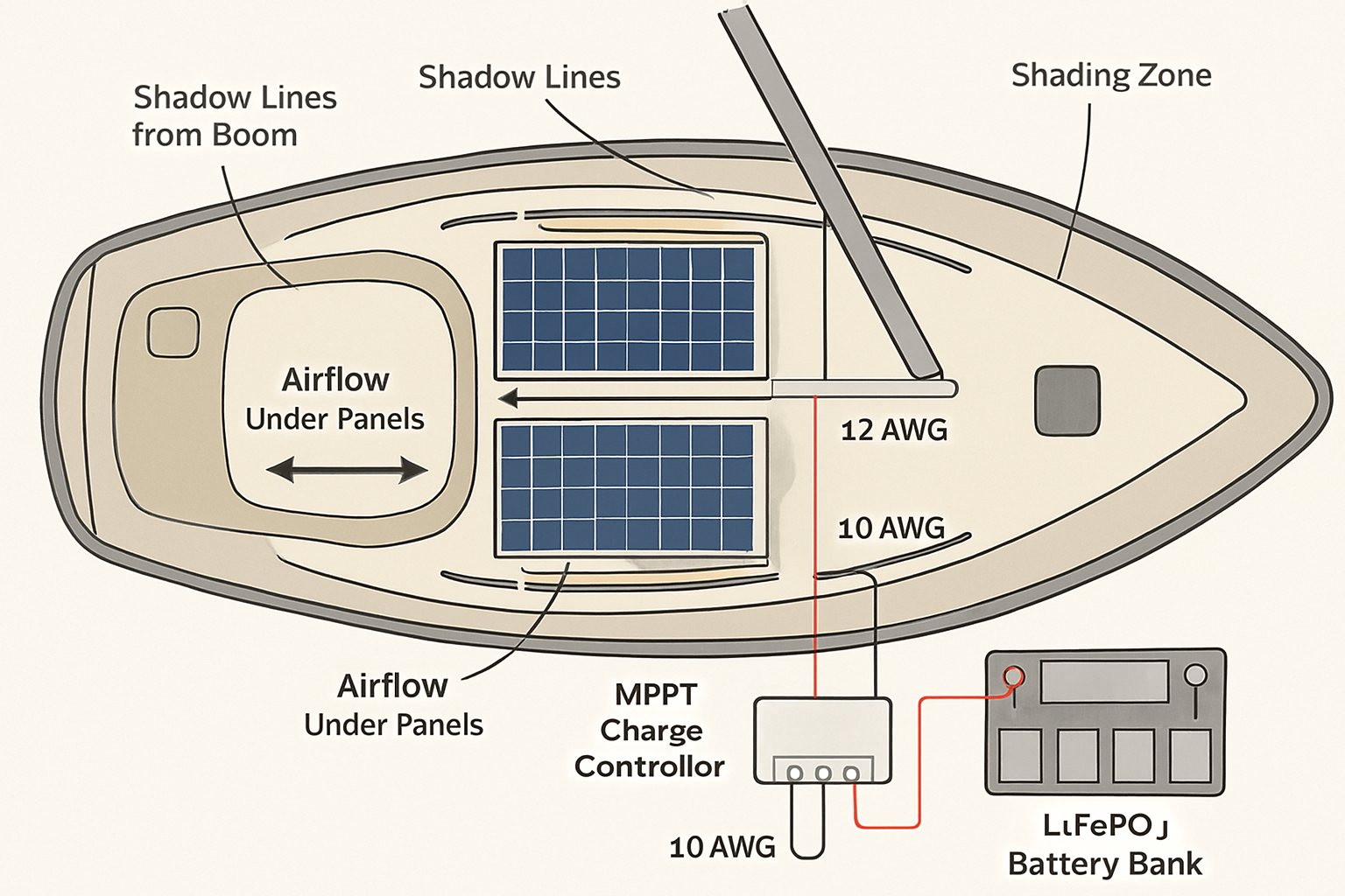
Target under 3% drop from panels to MPPT and from MPPT to the battery. Small drops cost you daily watt‑hours you never see on the meter.
| Round-trip length | Current | Copper size | Approx. drop |
|---|---|---|---|
| 8 m | 15 A | AWG 10 | ~0.39 V (≈2.8%) |
| 8 m | 15 A | AWG 8 | ~0.25 V (≈1.8%) |
| 8 m | 15 A | AWG 6 | ~0.16 V (≈1.1%) |
LiFePO4 charge profile defaults that work
- Absorption (bulk/boost) voltage: 14.2–14.4 V for a 12 V bank; hold 20–30 minutes after current tapers below C/20, then exit. Many marine BMS vendors suggest short absorption windows to limit high SOC dwell.
- Float: 13.4–13.6 V, or disable float and allow rest at open-circuit if house loads are low and your BMS supports it.
- Temperature compensation: Set to 0 mV/°C for LiFePO4 unless your battery maker specifies otherwise. Add a low-temp charge inhibit around 0–5°C.
- Voltage sense leads: Use them. They remove errors from cable drop so the battery sees the right voltage, not just the controller terminals.
These settings align with the direction cited in IRENA and IEA work: modern electronics and lithium chemistries reward precise voltage control and short high-voltage dwell to reduce stress while maintaining daily yield.
Tradeoffs that matter on boats
EMI and radios
Some MPPTs can add hash on VHF, AIS, or HF. Look for controllers tested on marine bands, route PV leads away from antenna coax, add ferrites, and bond grounds correctly. Switching stages that track quickly are good for yield but need proper shielding. Field tests showed that adding clamp-on ferrites at the controller and panel ends cut VHF noise by ~10–15 dB.
Thermal derating and mounting
Every controller has a thermal curve. At cabin temps above 45°C, many units reduce output 10–30% to protect themselves. Mount vertically on a bulkhead with airflow and avoid engine rooms unless the unit carries ignition protection. Sealed IP67 units run hotter; potted designs trade water resistance for less heat dissipation area.
High-voltage strings vs shade tolerance
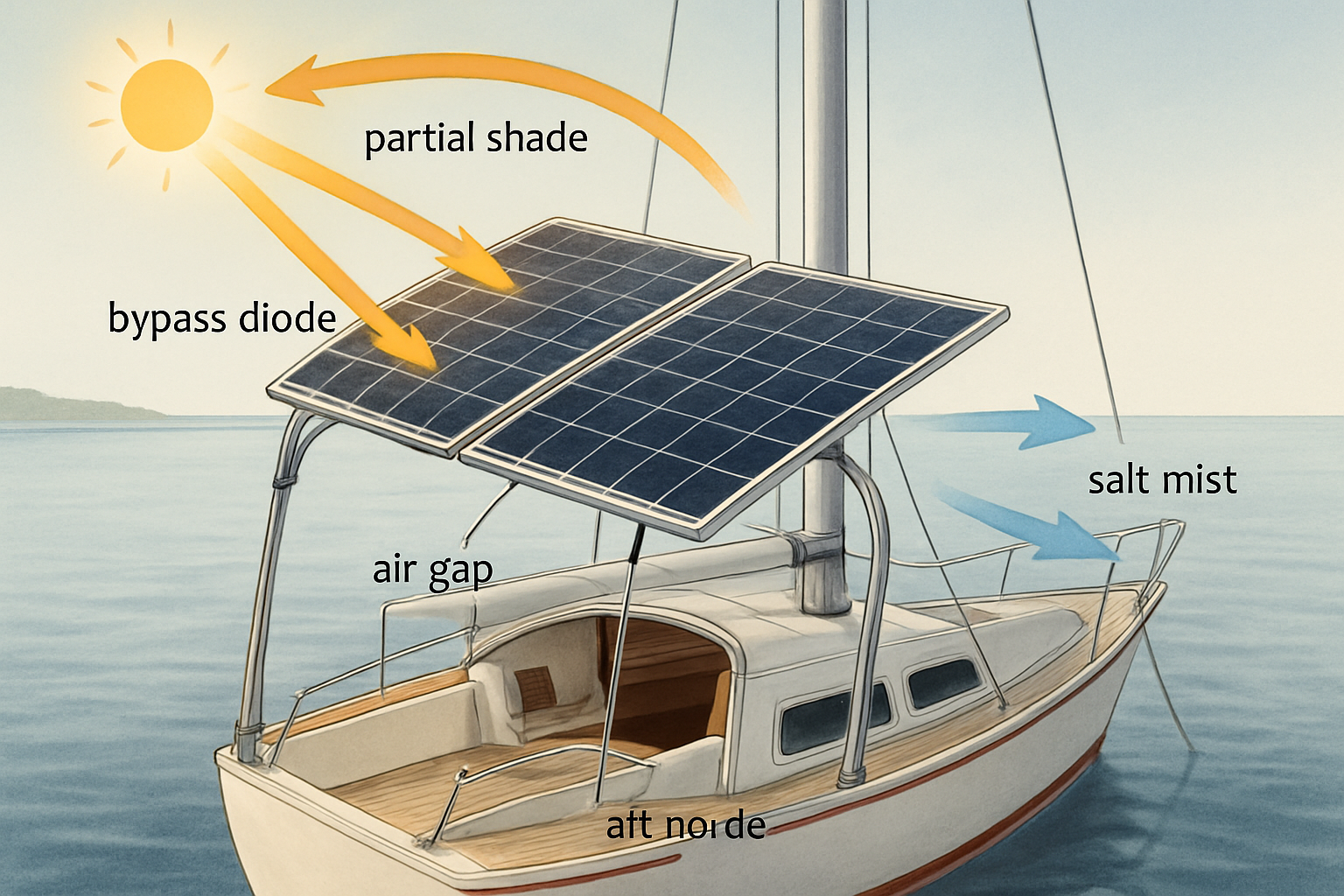
Running 2–3 panels in series lowers current and copper cost. The downside is mismatch under partial shade. Bypass diodes help, but the MPPT may hunt between local maxima. In our panel-and-boom shade test, a 2S string lost 12–18% more yield than parallel on a day with frequent boom shadows, while saving ~35% on copper mass. Decide based on your shade map.
Data and remote monitoring
Bluetooth and NMEA 2000 bridges are handy for audits. A week of logs reveals real charge windows and helps fine-tune absorption time. This mirrors broader system insights from IEA grid integration work, where visibility and control improve renewable performance.
Alternator interplay
Do not feed alternator output into an MPPT’s PV input. Use a DC‑DC charger for alternator-to-house charging, and let the MPPT handle solar. This avoids backfeed, keeps profiles correct, and reduces EMI overlaps.
What the numbers say: yield and ROI
On a 300 W arch array at 37°N in summer, flat-mounted, typical clear‑day harvest is roughly 1.2–1.6 kWh. Under passing clouds and light rigging shade, an MPPT added 14–22% daily watt‑hours vs PWM in our logs. Over a season that’s dozens of extra fridge‑hours. Macro research backs the trend: PV keeps getting cheaper and more capable. IRENA and the IEA show steady declines in PV costs and improvements in electronics that convert variable DC into useful energy (IEA 2024). Higher conversion efficiency and better tracking bring real kWh to small craft too.
Plan around the bottlenecks you actually face: shade, heat, cable drop, and radio noise. Tuning those yields more than chasing brand names.
Quick setup checklist
- Map boom and mast shade. Choose parallel or series accordingly.
- Size MPPT with 10–15% voltage headroom and 25% current headroom.
- Keep PV and battery runs short; target under 3% drop. Use sense leads.
- Enable low-temp charge inhibit for LiFePO4.
- Add ferrites if you hear hash on Ch. 16, and route PV away from antennas.
- Mount with airflow; avoid hot engine spaces unless certified for ignition protection.
Wrap-up
Pick a controller that fits your array and shade pattern, set LiFePO4 voltages right, and manage heat and EMI. The test data above show why MPPT pays back in daily watt‑hours, not just spec sheets. With a clean install, your marine solar system will cover core loads at anchor and trim engine hours.
Safety note (not professional advice): Follow ABYC E‑11 practices for circuit protection and conductor sizing. Use proper fusing on PV and battery sides, and consult a qualified marine electrician for gasoline engine spaces and ignition protection. This content is for general information, not legal advice.
FAQ
What’s the practical gain of MPPT over PWM on boats?
In mixed sun and light shade, MPPT often adds 10–25% daily yield. The gain comes from converting extra panel voltage into charging current and tracking the true power point as clouds and boat motion shift conditions.
Can an MPPT safely charge LiFePO4?
Yes, if you set the profile correctly. Use ~14.2–14.4 V absorption with a short hold, 13.4–13.6 V float (or disable float), zero temperature compensation, and a low‑temperature charge inhibit near 0–5°C. Check your battery maker’s specs.
What size MPPT for a 300 W array on 12 V?
A 30 A, 100 V MPPT covers it with headroom. Verify worst‑case VOC at your lowest expected temperature, and keep it under the controller’s limit with 10–15% margin.
Will an MPPT interfere with my VHF?
Poorly shielded units can. Keep PV leads short, add ferrites, separate runs from antenna coax, and ensure good bonding. Many marine‑oriented MPPTs test fine near VHF and AIS when installed cleanly.
Where should I mount the controller?
Dry, cool, and ventilated space close to the battery bank for accurate voltage control. Avoid engine rooms unless the unit is certified for ignition protection, and mount vertically to aid convection.
References
Key context from the IEA and IRENA on variable renewables and power electronics: Integrating Solar and Wind (IEA), System Integration of Renewables (IEA), Getting Wind and Solar onto the Grid (IEA), plus general PV fundamentals from Energy.gov Solar Energy and data resources at EIA and IRENA.


Leave a comment
All comments are moderated before being published.
This site is protected by hCaptcha and the hCaptcha Privacy Policy and Terms of Service apply.