Short-circuit testing protocols turn design intent into verified protection. You confirm that breakers, fuses, relays, BMS limits, and inverters trip at the right current and time, and that selective coordination holds. This piece focuses on practical, non-destructive methods to validate short-circuit settings and relay trip settings in PV+ESS and off-grid systems, with clear acceptance criteria and records you can defend.

What to validate and why timing matters
Trip setting validation checks three things: pickup accuracy, operating time, and selectivity. In PV+ESS, fault current is often limited by inverters and BMS, so timing becomes as critical as current magnitude. You want the closest device to the fault to act fast, while upstream devices hold.
- Pickup: Does the device sense overcurrent at the intended threshold?
- Time: Does the operation match the time-current characteristic (TCC)?
- Selectivity: Do upstream devices remain closed during downstream faults?
Protection timing also links to system stability. According to Grid Codes for Renewable Powered Systems, critical clearing time (CCT) determines how fast faults must be cleared to maintain stability; these studies feed protection time settings and validation targets. For networks with high distributed energy resources (DER), screening and studies guide acceptable interconnection behavior, including protection performance. The System Integration of Renewables report notes that “screens” and location-specific studies are needed as DER penetration rises, reinforcing the need to test and confirm settings in situ.
Where PV and storage change power flow direction, protection miscoordination risk grows. The China Power System Transformation work highlights the need for improved planning and validation practices as systems evolve. Field validation ensures your protection still performs after upgrades, firmware changes, or reconfiguration.
Safe instruments and setups for non-destructive testing
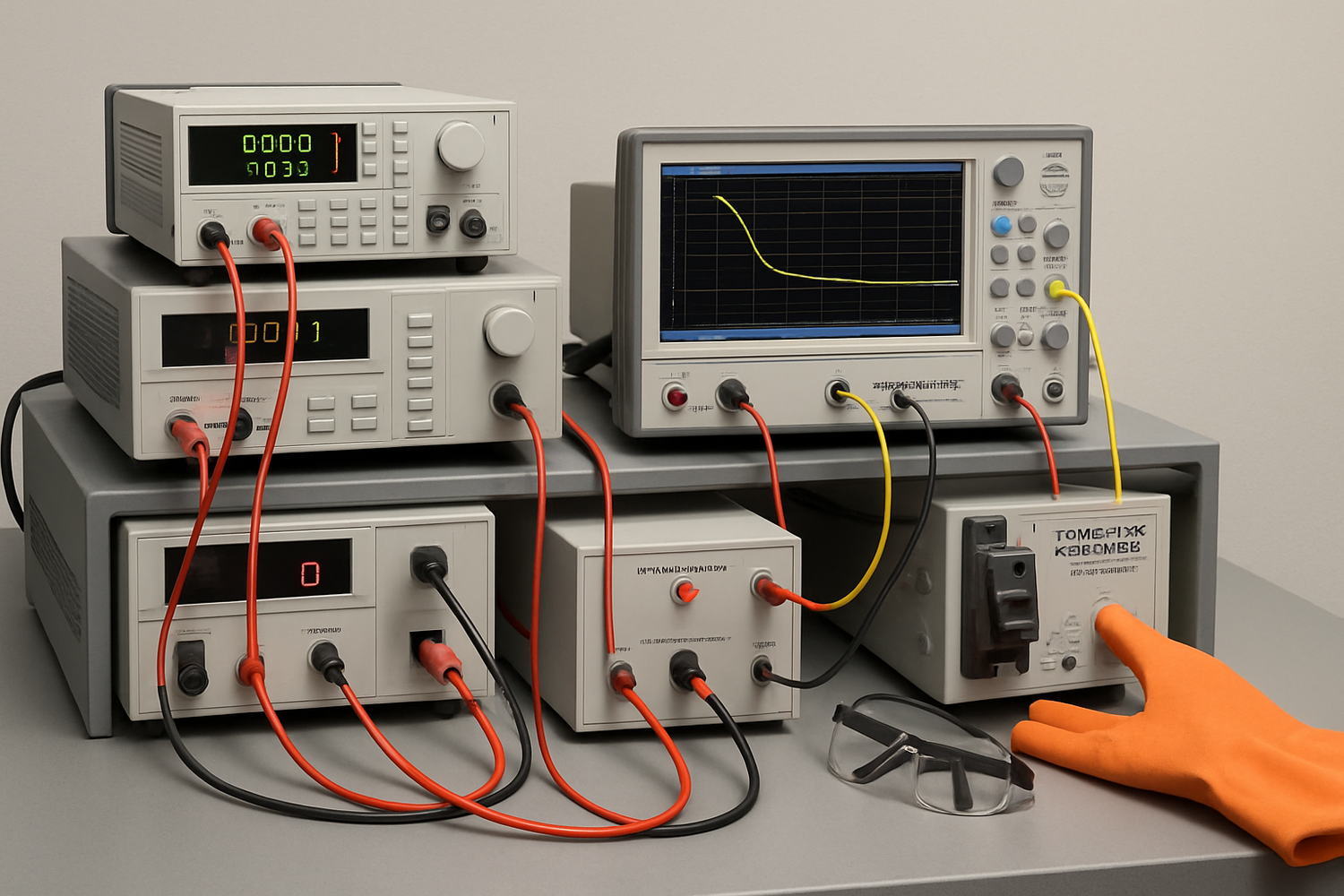
Core equipment
- Primary current injection source (AC/DC) with current limit, for breakers and bus sections.
- Secondary injection test set for relays (50/51, 50N/51N, 46, etc.).
- Programmable electronic load for DC fault simulations and inverter foldback tests.
- Insulation resistance tester and micro-ohmmeter for preliminary checks.
- RCD/GFCI tester with 0°/180° phase capability.
- Oscilloscope or power analyzer with current probes (≥10 kHz bandwidth) and a logging multichannel recorder.
- Arc-rated PPE, insulated mats, barriers, and lockout/tagout (LOTO) hardware.
Non-destructive approach
- Use current-limited sources and short pulses (e.g., 50–200 ms) to characterize instantaneous trips without thermal damage.
- For fuses, use staged current and stop at the “pre-arcing” threshold gleaned from datasheets to avoid melting during tuning.
- Simulate downstream faults at the device terminals to avoid stressing cables and connectors.
Good practice aligns with broader safety and performance goals highlighted by the U.S. Department of Energy’s Solar Energy resources: verify performance efficiently while controlling risk. Also mind efficiency requirements of associated accessories; for example, IEA’s work on external power supplies shows how standardized test methods shape reliable verification of electronic behavior (Transforming Global Markets for Clean Energy Products).
Stepwise protocols: how to test short-circuit settings
Pre-test checklist
- Capture nameplate data, firmware versions, and all current settings.
- Export TCC curves and manufacturer limits for every protection device.
- Draw a one-line with test points and isolation boundaries.
- Apply LOTO; confirm absence of voltage; verify correct polarity on DC paths.
- Measure insulation resistance and contact resistance to set a clean baseline.
DC side: batteries, DC breakers, and fuses
- Breaker instantaneous trip: Apply 4–8× In pulse via current injector or electronic load in constant-current mode. Start at 3× In and increase until instantaneous element operates. Record peak A, operate ms, and contact bounce.
- Thermal region: Apply 1.5–2× In with a time limit that respects cable ampacity. Confirm operate time matches the TCC band.
- Fuse characterization: Use a controlled current rise to approach the minimum melt line, then stop. Confirm I²t margins against cable and BMS limits. For acceptance, any intentional melt test must be done with spare holders and shields.
- BMS current limit: Step current to the specified limit and hold; capture foldback time and recovery behavior. Ensure OCPD still clears faults below the BMS hard limit.
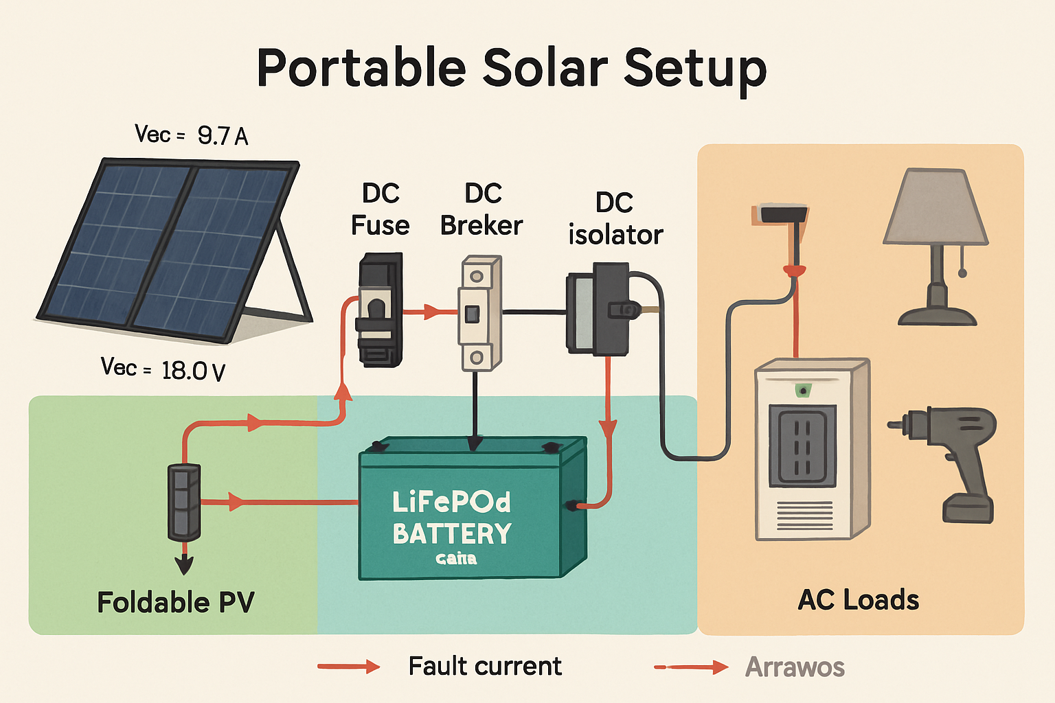
PV strings and combiners
- String fault simulation: Use an electronic load to pull current from the combiner output while backfeeding is blocked. Verify gPV fuses in the affected string see ≥2× In and operate per datasheet timing, while adjacent strings do not nuisance-trip.
- Reverse current check: Confirm that reconfiguration or parallel strings cannot exceed fuse ratings; align with DER screening principles noted by the IEA.
AC side: inverters, MCCBs, and RCD/GFCI
- Inverter-limited short-circuit: With loads isolated, step the electronic load at the AC bus to 150–300% of inverter rating for 100–200 ms. Capture peak fault current and decay to foldback. Confirm downstream breakers trip within their instantaneous zone while upstream remain closed. This validates selectivity under limited fault current.
- MCCB primary injection: Inject 5–10× In for instantaneous verification, and 1.5–3× In for short-time. Compare to TCC with ±10–20% time tolerance, as agreed in the test plan.
- RCD/GFCI: Test at 0.5×/1×/5× IΔn with 0°/180° phase angles. Typical 30 mA devices should clear ≤300 ms at 1× and ≤40 ms at 5×. Confirm trip on both half-cycles.
Relays and coordination
- Secondary injection: Inject pickup multiples (1.05×, 2×, 5×) on 50/51 and 50N/51N elements. Validate operate time against the selected curve (IEC/IEEE inverse, very inverse, etc.) within ±5–10%.
- Logic checks: Test inhibit signals (e.g., inverter status), breaker failure logic, and lockouts. Confirm resets and event logs stamp accurate time.
- Coordination test: Stage a downstream fault with the upstream time dial increased by one step as a sensitivity check. The downstream device must operate while upstream stays closed.
Acceptance criteria and quick reference
Set acceptance bands before testing. Use manufacturer curves as the primary reference and define tolerances that reflect instrument uncertainty and operating temperature. The table below shows example criteria for a 48 V DC + 230/120 V AC PV+ESS. Replace values with your device data.
| Test | Setup | Stimulus | Expected response | Pass criteria |
|---|---|---|---|---|
| DC breaker (125 A, C-curve, DC-rated) | Primary injection | 5× In (≈625 A), 50–100 ms pulse | Instantaneous open in tens of ms | Operate ≤80 ms; contacts fully open; no reclose |
| PV fuse (15 A gPV) | Electronic load | 3× In (≈45 A) sustained | Melt in 1–4 s (datasheet band) | Trip within datasheet band ±25%; holder intact |
| Inverse-time relay (50/51) | Secondary injection | 2× pickup | Operate per selected curve (e.g., ≈3 s) | Time within ±10%; correct contact state |
| RCD/GFCI (30 mA) | RCD tester | 1× IΔn at 0°/180° | Trip ≤300 ms | Each angle ≤200 ms target; 5× ≤40 ms |
| Inverter short-circuit limit | AC electronic load | Step to 200% for 100–200 ms | 1.5–3× rated current then foldback | Matches datasheet band; downstream OCPD trips first |
| Contact resistance (bus/CB) | Micro-ohmmeter | 10–100 A DC | Low μΩ consistent across poles | ≤ baseline +20% and within maker limit |
Timing targets should also respect system-level clearing needs. As noted by IRENA’s grid code analysis, CCT studies guide protection time settings for stability. In distribution with DER, screening identified by the IEA informs which feeders require tighter coordination.
Documentation that stands up to audits
- Record: Device ID, settings, serial/firmware, ambient temperature, and all test stimuli/responses.
- Capture: Oscilloscope screenshots of current and voltage with cursors on pickup and trip instants.
- Compare: Overlay measured points on the manufacturer TCC; store the annotated plot.
- Decide: Pass/fail against pre-set criteria; note corrective actions.
- Archive: Keep files, photos, and tester calibration certificates.
Establish revalidation triggers: after firmware updates, hardware changes, altered feeder topology, or measured drift in contact resistance. This echoes the planning mindset in China Power System Transformation, where evolving systems require iterative reassessment. For new DER connections, align acceptance with local screening rules referenced by the IEA.
Field example: inverter-limited fault and coordination
Setup: 5 kW hybrid inverter, downstream 32 A AC breaker (C-curve), upstream 63 A breaker (D-curve). Electronic load steps to 10 kVA for 150 ms.
- Measured peak fault current: 2.4× inverter rating for 120 ms; then foldback to 1.1×.
- Downstream breaker trip: 38 ms; upstream held.
- Repeat at 1.8×: downstream did not instantaneous-trip; short-time region cleared at 210 ms, still selective.
Result: Coordination achieved across both instantaneous and short-time regions under inverter-limited fault current. This confirms settings without stressing cables or the inverter.
Common testing pitfalls (and fixes)
- Using unlimited sources: Add current limiting and pulse timing to prevent damage.
- Ignoring temperature: Record ambient; adjust tolerances for cold/hot conditions that shift thermal curves.
- Testing at wrong point: Always inject at device terminals to avoid line impedance masking true pickup.
- Skipping 0°/180° on RCD tests: Half-cycle dependence can hide borderline devices.
- No reference curves on hand: Download curves in advance; without them, you cannot judge “good enough.”
Standards-aligned perspective
Protection validation is not done in isolation. Use timing objectives consistent with system stability and safe operation. The IRENA work shows how CCT and measured fault traces inform clearing targets. The IEA stresses enhanced screening as DER grows; your test plan should reflect feeder-specific conditions. Broader product verification trends, like harmonized test methods noted by the IEA, support consistent, repeatable results. For general solar context and safety topics, consult the U.S. DOE’s Solar Energy resources.
Disclaimer: Electrical testing involves hazardous energy. Use qualified personnel, certified instruments, and follow applicable codes. Non-legal advice.
FAQs
How can I test short-circuit settings without blowing fuses?
Use current-limited injection and short pulses to verify instantaneous pickup and timing. For fuses, approach the minimum melt line and stop. Validate with secondary injection on relays and electronic loads for inverter-limited conditions.
How often should I revalidate trip settings?
At commissioning, then after any firmware or settings change, topology changes, or annually for critical assets. Add event-driven checks if contact resistance drifts or nuisance trips appear.
How do I validate relay trip settings if I cannot create full fault current?
Use secondary injection to reproduce pickup multiples and timing. Correlate to primary values through CT ratios. Confirm logic, block/inhibit inputs, and event timestamps.
Do inverter fault limits change the pass/fail criteria?
Yes. With 1.5–3× rated fault current and short duration, prioritize instantaneous sensitivity and coordination at lower multiples. Confirm downstream devices still clear within acceptable time bands.
What records should I keep for audits?
Device IDs, settings, firmware, calibrated instrument IDs, raw captures, TCC overlays, and signed pass/fail sheets. Keep a revision history tied to feeder reconfiguration or DER additions.
Leave a comment
All comments are moderated before being published.
This site is protected by hCaptcha and the hCaptcha Privacy Policy and Terms of Service apply.