Arc-faults on PV DC circuits start small and escalate fast. Hybrid inverters add battery, PV, and grid dynamics, so arc-fault detection needs smarter logic. This review breaks down AFCI algorithms, how hybrid control loops affect detection, and what mitigation strategies prove reliable in the field. You will see where each algorithm shines, where it struggles, and how to set realistic performance targets for solar safety.
What a DC Arc Looks Like in Hybrid Systems
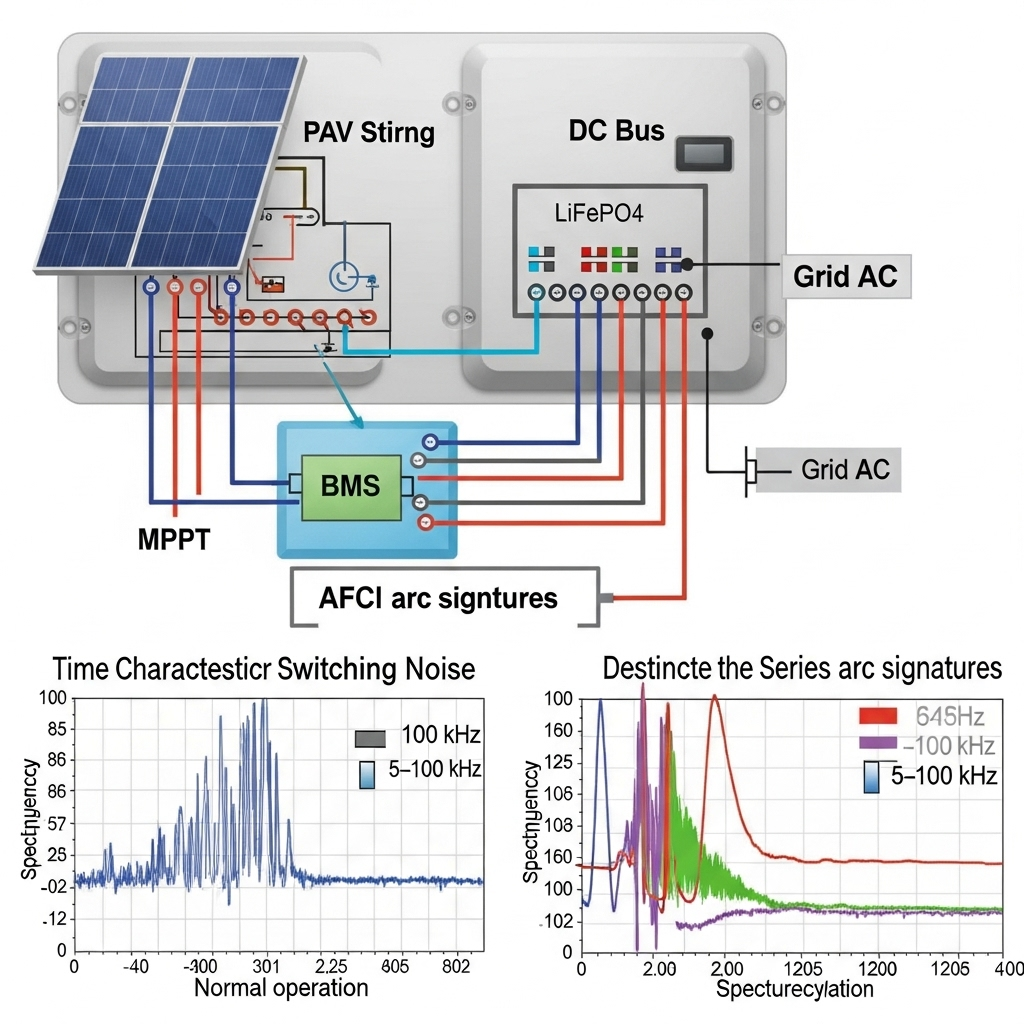
Series arcs often arise from loose connectors, cracked solder joints, or damaged cables. On a constant-voltage PV string, that arc introduces high-frequency noise, intermittent current drops, and a broadband signature that spreads across tens of kilohertz. A hybrid inverter complicates the waveform. The DC link couples PV and battery ripple. MPPT duty cycles and battery charge control add switching content that can mask a weak arc.
Grid-following control, common in distributed PV, continues to evolve and adds advanced services through software features in the inverter. As noted by the International Energy Agency, inverters provide more than conversion and increasingly support protection and visibility functions (System Integration of Renewables — IEA). That same digital flexibility enables stronger arc-fault detection and mitigation.
Microgrids highlight how sophisticated inverter control can coordinate safety and uptime. A U.S. Department of Energy project demonstrated autonomous restoration with grid-forming inverters and resilient coordination across connected microgrids (DOE SETO Success Story). While that project targeted resilience, it shows how layered controls and rapid decision loops can also support arc containment logic in hybrid platforms.
AFCI Algorithm Families and Their Signal Features
Most inverter arc-fault diagnosis stacks combine several detectors. Each watches different features to reduce blind spots. Below are practical families used in hybrid inverters today.
Time-domain thresholds
These track sudden current variance, repetitive di/dt bursts, and DC-link ripple spikes. The appeal is simplicity and low compute cost. The risk is sensitivity to normal transients like rapid MPPT changes or battery step responses.
Spectral and wavelet detectors
These measure energy in frequency bands where arcs radiate, often 5–100 kHz. Wavelets capture short bursts that Fourier averages can dilute. Careful notch filtering around inverter switching harmonics improves robustness in hybrids.
Model-based residuals
A physics model of the PV-battery-DC link predicts current and voltage. The algorithm compares measured signals with predictions. Persistent residuals flag anomalies consistent with a series arc. Parameter updates must follow temperature and state-of-charge changes.
Machine learning classifiers
ML blends multi-band spectral features, residuals, and time-domain cues. It can improve immunity to nuisance trips, provided the training set covers battery charge/discharge states, irradiance ramps, and inverter PWM patterns. On-device models stay compact to fit DSP or MCU resources.
Comparison at a Glance
| Algorithm | Key features | Typical detection time | Noise resilience in hybrids | Compute cost | False trip risk | Tuning tips for hybrids |
|---|---|---|---|---|---|---|
| Time-domain thresholds | Current variance, di/dt bursts, ripple index | 0.5–2.0 s | Low–Medium | Low | Medium–High | Sync with MPPT steps; rate-limit decisions around battery step loads |
| Spectral / wavelet | Energy in 5–100 kHz bands; wavelet bursts | 0.2–1.0 s | Medium–High | Medium | Medium | Notch inverter carrier and harmonics; adapt band gains by DC-link ripple |
| Model-based residual | PV-battery-DC link model residuals | 0.2–0.8 s | High | Medium–High | Low–Medium | Update model with SoC, temperature, and PV voltage class |
| Machine learning | Classifier on mixed features | 0.1–0.5 s | High | Medium–High | Low (with representative data) | Retrain with site logs; apply domain adaptation for new arrays |
The detection time ranges reflect lab conditions with clean labeling. Field performance depends on commissioning quality, sensor bandwidth, and inverter DSP load.
Hybrid-Specific Challenges that Shape AFCI
PWM and DC-link interactions
Hybrid inverters switch at tens of kilohertz. That carrier and its sidebands ride on the PV string current and voltage. Without notches or adaptive band selection, frequency-domain detectors can misclassify PWM sidebands as arcs. Model-based and ML logic reduces this risk by correlating sidebands with known gate timing.
Battery behavior and nuisance trip control
High-performance LiFePO4 storage has low internal resistance and stable voltage. That changes ripple and fault energy paths. A practical storage reference notes strong round-trip efficiency near the mid-90% range and long cycle life, which supports frequent cycling in hybrids (Ultimate reference: solar storage performance). Those traits are great for yield but can increase current step magnitudes during charge transitions. AFCI thresholds need hysteresis and short blanking windows around BMS-triggered current changes to prevent false trips.
DER-rich grids and protection limits
High levels of inverter-based resources reduce fault current and add bidirectional flow in distribution systems. Legacy protection schemes that rely on fault current magnitude can struggle (IEA: System Integration of Renewables). Inside a hybrid inverter, limited overcurrent headroom narrows the separation between normal and fault signatures. That pushes AFCI designs toward multi-feature fusion and faster, more certain classification.
Mitigation Strategies Inside Hybrid Inverters
Fast isolation and safe shutdown
After detection, the controller must quench the arc and remove energy. Typical steps include: ramping down MPPT current, commanding the battery to zero current, opening DC contactors or solid-state relays, and engaging rapid-shutdown functions on the array. Product designs align with widely adopted safety goals in standards such as UL 1699B and IEC 63027, which target detection and interruption of PV DC arcs.
Active arc extinction through control
Hybrid inverters can reduce the DC-link energy that feeds the arc. They can shift duty cycles to raise arc voltage and collapse current, inject a short controlled ramp-down, and momentarily increase damping on the input stage. Many units also pause battery power transfer so the PV string does not see a low-impedance sink while the arc collapses.
Coordination with storage and BMS
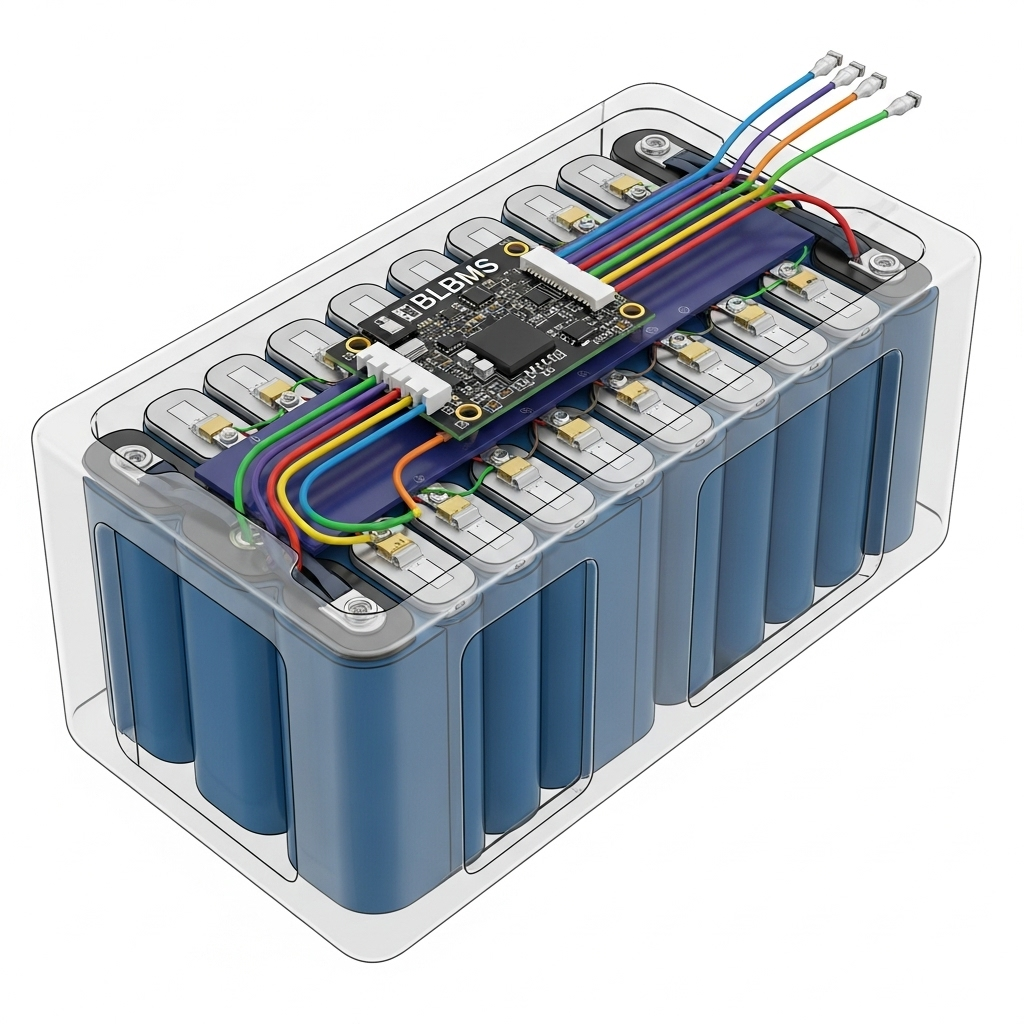
Mitigation works better with BMS handshakes. AFCI logic requests a rapid but smooth current limit. The BMS confirms acceptance and shares state-of-charge and temperature. This avoids abrupt steps that would otherwise look like arc signatures. Storage performance references for LiFePO4 point to stable mid-band voltage, which simplifies closed-loop damping during the event (Solar storage performance reference).
How to Evaluate AFCI Performance
Key metrics to ask for
- Detection time: typical and worst case across irradiance and temperature. Targets of 0.2–1.0 s are common in modern designs.
- Probability of detection over arc gap sizes and string voltages. Ask for coverage curves not just a single point.
- Nuisance trip rate under defined MPPT sweeps, battery step loads, and grid events. Express per operating hours or MWh.
- Hold-off and hysteresis strategy that prevents chatter during dynamic conditions.
Test methods that reflect hybrid reality
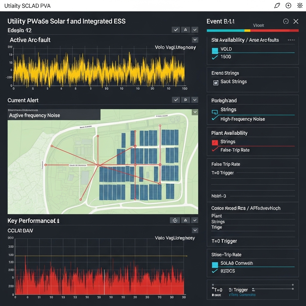
Lab validation should use an arc generator, line impedance stabilization, and programmable PV emulators. Include frequency-injection to emulate EMI sources. Hardware-in-the-loop helps sweep duty cycles, DC-link capacitance changes, and BMS current limits. Field pilots should log raw high-rate data so ML or threshold refinements can retrain with local patterns.
The IEA notes that DER visibility and controllability are vital for reliability (IEA report). That aligns with the need to record event waveforms, flag causes, and feed improvements back into AFCI firmware.
Linking AFCI with broader inverter design
IEA research on solar energy also highlights the central role of inverters as the interface for new functions (IEA: Solar Energy Perspectives). AFCI is part of that toolbox. As platforms add grid-forming modes, blackstart features, and microgrid coordination, AFCI must stay fast and decisive without tripping on those advanced behaviors. The DOE microgrid success story demonstrates that layered controls can coordinate complex responses reliably (DOE SETO Story).
Procurement and Engineering Tips
- Request algorithm transparency: primary features used, band notches, and model update cadence.
- Ask for hybrid-specific benchmarks: repeated charge transitions, MPPT step tests, and DC-link capacitance variations.
- Verify firmware update and rollback. Safe updates keep AFCI tuned without risking uptime.
- Plan data access: high-rate waveform snapshots around every AFCI event for root-cause analysis.
- Align storage specs with detection goals: LiFePO4 packs with known C-rates and BMS step limits simplify tuning (reference).
What This Means for System Safety and Uptime
Strong AFCI algorithms shrink arc energy, protect hardware, and support availability. Hybrid systems gain extra control levers for mitigation, yet face more noise and dynamic behavior. A multi-feature stack that mixes spectral energy, residuals, and a compact classifier tends to offer the best balance. Field data logging and periodic retraining close the last gap.
Independent energy bodies continue to stress the role of inverter-based resources and digital controls in reliable grids. Reviews and updates from agencies such as IRENA, the IEA, and the EIA underline the need for protective functions that keep pace with rapid PV and storage adoption. AFCI belongs in that conversation.
Safety and compliance disclaimer: This technical content is for information only, not legal advice. Always follow the latest applicable codes and product standards.
FAQ
How do AFCI algorithms in hybrid inverters differ from PV-only designs?
They must handle battery-driven current steps and DC-link ripple, plus grid events. Hybrid units use notches around inverter carrier frequencies, model updates tied to state-of-charge, and brief hold-off windows during BMS handshakes to avoid false trips.
Can ML-based AFCI run on a low-cost DSP?
Yes, with compact models. Feature extraction stays lightweight: few wavelet bands, simple residuals, and a small classifier. Many designs quantize weights and use fixed-point arithmetic to fit timing budgets.
Do high C-rate batteries increase false trips?
They can. Fast charge/discharge steps raise di/dt and ripple. Proper hysteresis, short blanking intervals around commanded steps, and BMS coordination reduce nuisance trips. Storage behavior data, such as LiFePO4 voltage stability, also helps tune thresholds (storage performance reference).
What detection time is realistic for reliable arc-fault detection?
Sub-second is achievable in many hybrids. A range of 0.2–1.0 s is common in lab conditions. Field values depend on sensor bandwidth, DSP load, and commissioning quality.


Leave a comment
All comments are moderated before being published.
This site is protected by hCaptcha and the hCaptcha Privacy Policy and Terms of Service apply.