As the solar energy market becomes increasingly global, installers frequently encounter components designed to meet International Electrotechnical Commission (IEC) standards. In the United States, however, all electrical installations, including rooftop solar, must adhere to the National Electrical Code (NEC). This creates a critical challenge: how to correctly adapt an IEC-based earthing scheme to meet NEC grounding requirements. Proper grounding is fundamental for safety, protecting against electrical shock and fire, and ensuring the stable operation of your solar energy system.
Understanding the Core Differences: IEC vs. NEC Grounding Philosophies
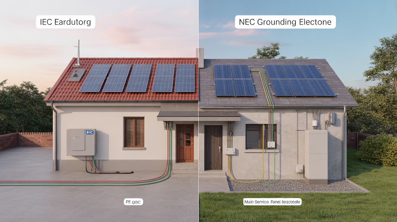
At first glance, IEC “earthing” and NEC “grounding” seem to describe the same concept. While both aim to enhance safety, they approach it with different philosophies, terminology, and application methods. Understanding these distinctions is the first step toward a compliant installation.
IEC Earthing: A Focus on Fault Protection
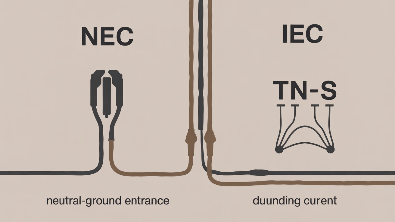
The IEC 60364 standard defines several earthing systems, identified by two-letter codes like TN, TT, and IT. The most common system, TN, uses a direct connection to earth at the supply transformer and connects the equipment chassis to the neutral conductor. The primary objective is to create a low-impedance path for fault current. This ensures that a fault, such as a short circuit, will draw enough current to quickly trip a circuit breaker or blow a fuse, disconnecting the power and preventing electric shock.
NEC Grounding: A Comprehensive Safety System
The NEC, which is law in the United States, treats grounding as a more comprehensive system. It distinguishes between two critical functions: system grounding and equipment grounding. System grounding involves connecting one of the current-carrying conductors of the electrical system (usually the neutral) to the earth. This stabilizes voltages and provides a path for fault current. Equipment grounding involves connecting all non-current-carrying metallic parts of the system—such as inverter chassis, module frames, and racking—together and to the earth. This ensures that no exposed metal can become energized during a fault.

Key Terminological and Practical Distinctions
The different philosophies lead to different terms and practices. A direct comparison clarifies the conversion process. As noted in an IEA report, Transforming Global Markets for Clean Energy Products, harmonizing test procedures and standards is a significant challenge for globally traded products like solar components.
| Concept | IEC Terminology | NEC Terminology | Primary Function |
|---|---|---|---|
| Safety Conductor | Protective Earth (PE) | Equipment Grounding Conductor (EGC) | Connects all metallic equipment to ground to prevent shock. |
| Connection to Earth | Earthing Conductor | Grounding Electrode Conductor (GEC) | Connects the system's grounding electrode to the service equipment. |
| Conductor Color | Green-and-yellow striped | Green, green with yellow stripe, or bare copper | Visual identification of the safety conductor. |
| Main Connection Point | Main Earthing Terminal | Grounding Busbar (in service panel) | Central point where all grounding conductors are connected. |
The Conversion Process: A Step-by-Step Approach for Rooftop Solar
Adapting an IEC-compliant product, such as a solar inverter, for a US rooftop installation requires a methodical approach. The goal is to use the IEC equipment's designated safety connection points within a fully realized NEC grounding system.
Step 1: System and Equipment Assessment
Begin by carefully reviewing all manufacturer documentation for the solar modules, inverter, and racking system. An IEC-certified hybrid inverter, for instance, will have a terminal marked with the “PE” symbol. This is the designated point for connecting the equipment grounding conductor. Identify all such points and understand the manufacturer's requirements before starting the installation.
Step 2: Establishing the NEC-Compliant Grounding Electrode System
The entire electrical system of the building must be connected to a grounding electrode system, which provides the physical connection to the earth. For a typical US residence, this system often uses a ground rod or the concrete-encased electrode (Ufer ground). Your solar installation's grounding system must be bonded to the building's existing grounding electrode system via the Grounding Electrode Conductor (GEC).
Step 3: Implementing Equipment Grounding
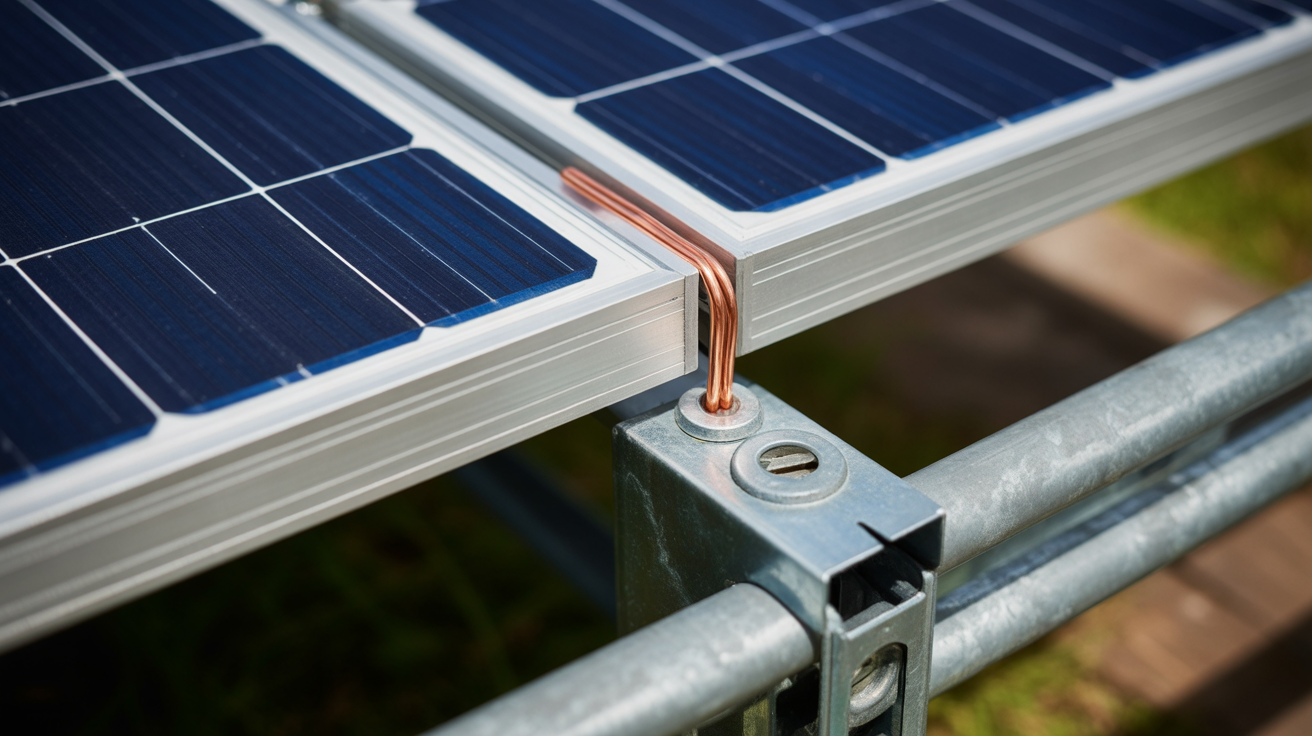
This is where the conversion truly happens. A continuous Equipment Grounding Conductor (EGC) must connect the chassis of every piece of metallic equipment. This includes the inverter, the frames of every solar module, and all sections of the metal racking. Use listed lugs and bonding hardware specifically designed for this purpose to ensure a reliable, long-lasting connection. This EGC is then run back to the grounding busbar in the main electrical panel, creating an unbroken path to ground.
Case Study: A Residential Rooftop Solar Installation
Examining a real-world scenario helps illustrate the practical application of these principles.
The Scenario: IEC-Certified Components in a US Home
An installer is tasked with setting up a residential off-grid solar solution. The system includes a powerful hybrid solar inverter and a high-performance LiFePO4 battery storage system. The inverter is a global model with IEC certifications and a manual that refers to “PE” connections. The local Authority Having Jurisdiction (AHJ), however, requires strict adherence to the latest edition of the NEC.
The Solution: Bridging the Standards Gap
The installer correctly identified the inverter's PE terminal as the designated connection point for the NEC's EGC. They ran a properly sized copper EGC from this terminal to a bonding lug on the solar array's racking. Each module frame was then bonded to the racking using listed hardware. The EGC was continued from the array to the grounding busbar in the home's main service panel. This created a continuous, low-impedance path to ground for all metallic components, satisfying the AHJ and ensuring the system's safety. The result was a fully compliant installation that seamlessly integrated top-tier, IEC-certified equipment into the NEC framework.
Common Pitfalls and Best Practices
Navigating the differences between IEC and NEC standards requires attention to detail. Avoiding common mistakes is crucial for safety and passing inspection.
Misinterpreting Conductor Colors
Never assume conductor colors are interchangeable. While both standards use green or green with a yellow stripe, the specific application can differ. Always verify the function of a conductor rather than relying solely on its color. In the US, the EGC must be green, green with a yellow stripe, or bare.
Improper Bonding
Simply bolting module frames to a metal rack does not guarantee a proper bond. Anodized aluminum frames and powder-coated racks can have non-conductive surfaces. Use specialized bonding hardware that penetrates these coatings to create a solid electrical connection. This ensures the entire metal structure is part of the equipment grounding path.
Overlooking Local Code Variations
The NEC provides a baseline for safety, but local jurisdictions can and do make amendments. Always consult with the local AHJ to understand any specific requirements for your area before beginning an installation. Providing reliable and scalable energy solutions means adapting to these regional regulatory landscapes.
A Forward Look at Grounding Standards
The renewable energy industry is a prime example of global collaboration. As technologies like residential energy storage systems and advanced solar inverters are developed and deployed worldwide, the need for harmonized standards becomes more apparent. Organizations are continually working to align international codes, but for now, a deep understanding of both IEC and NEC practices is essential for installers. The ability to correctly convert between these standards is a hallmark of a professional and ensures that homeowners receive a system that is not only powerful and efficient but also unequivocally safe.
Frequently Asked Questions
Can I use an IEC-certified inverter in the US?
Yes, provided it is also listed by a Nationally Recognized Testing Laboratory (NRTL), such as UL, for use in the United States. The listing ensures it has been tested to meet US safety standards. The installation, particularly the grounding, must always follow the NEC.
What is the main difference between a PE conductor and an EGC?
Functionally, they serve the similar safety purpose of providing a path for fault current. The key difference lies in the codes that define them. The Protective Earth (PE) conductor is defined by IEC standards, while the Equipment Grounding Conductor (EGC) is defined by the NEC. This results in different requirements for sizing, identification, and installation methods.
Do I need a separate ground rod for my rooftop solar array?
Typically, no. The NEC requires bonding the solar equipment's grounding system to the building's existing grounding electrode system. This creates a single, unified ground reference for the entire structure. A new ground rod might be required in specific situations, such as for large ground-mounted arrays or if the existing system is found to be inadequate, but this is uncommon for rooftop installations.
Leave a comment
All comments are moderated before being published.
This site is protected by hCaptcha and the hCaptcha Privacy Policy and Terms of Service apply.