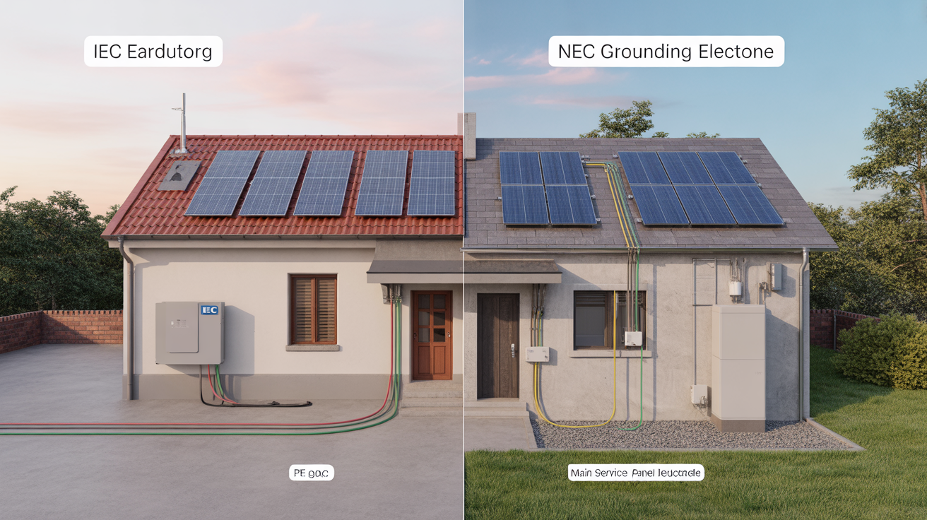
Proper system grounding is fundamental to the safety and performance of any solar photovoltaic (PV) or energy storage system (ESS). It protects people from electric shock and equipment from damage. When you work in the global energy market, you will encounter two primary sets of standards that govern these practices: the National Electrical Code (NEC) and the International Electrotechnical Commission (IEC) standards. While both aim to ensure safety, their philosophies, terminology, and prescribed methods differ significantly. Understanding these differences is not just an academic exercise; it's a practical necessity for designers, installers, and engineers.
Core Philosophies: What Drives NEC and IEC Grounding Rules?
At first glance, NEC grounding and IEC earthing appear to be two ways of saying the same thing. The core objective—creating a safe path for electrical current in the event of a fault—is indeed shared. Yet, the path to achieving that objective is where they diverge.
The NEC Approach: A Focus on Fault Current Paths
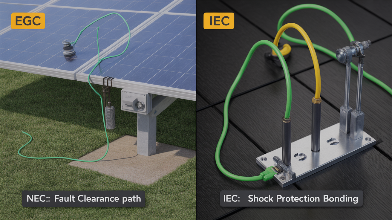
The NEC, which is the benchmark for electrical installations in the United States, takes a highly prescriptive approach. It provides detailed, specific rules on how to ground a system. The primary philosophy behind NEC grounding is to create a low-impedance path for fault current to flow back to its source. This ensures that a fault will draw enough current to quickly trip an overcurrent protection device (OCPD), like a circuit breaker or fuse, de-energizing the circuit. Key terms you will constantly see in the NEC include:
- Grounded Conductor: A current-carrying conductor that is intentionally connected to the earth, such as the neutral wire in an AC system.
- Equipment Grounding Conductor (EGC): A conductor that bonds all non-current-carrying metal parts of the system together and back to the system's grounded point. Its job is to carry fault current.
- Grounding Electrode Conductor (GEC): The conductor that connects the system's grounded conductor and/or the EGC to a physical grounding electrode (like a ground rod) in the earth.
This prescriptive method leaves little room for interpretation, aiming for uniformity and predictability in safety outcomes. For a deeper look into the specific roles of these conductors, you can review this resource: Decoding NEC equipment grounding and IEC protective earth.
The IEC Approach: A Focus on Touch Voltage Protection
The IEC standards, applied in Europe and many other parts of the world, are generally more performance-based. Instead of dictating the exact methods, IEC standards focus on achieving a specific safety outcome: protecting individuals from dangerous touch voltages. A touch voltage is the voltage that can appear between a person's hand and feet if they touch an energized piece of equipment during a fault. The IEC framework is designed to ensure this voltage remains below a safe threshold (typically 50V in dry conditions). This is achieved through various system earthing arrangements, identified by two-letter codes:
- TN Systems (Terre-Neutre): The source is directly earthed, and the installation's exposed conductive parts are connected to the neutral conductor.
- TT Systems (Terre-Terre): The source has its own earth connection, and the installation has a separate, independent earth electrode.
- IT Systems (Isolé-Terre): The source is either isolated from earth or connected through a high impedance, while the installation's metal parts are earthed.
This approach provides more flexibility in design but requires a deeper engineering analysis to prove that safety objectives are met.
Key Terminology Differences: A Quick Comparison
To navigate between the two standards, it helps to have a clear translator for the most common terms.
| NEC Term | IEC Term | Primary Function |
|---|---|---|
| Grounding | Earthing | The overall concept of connecting a system to the earth. |
| Equipment Grounding Conductor (EGC) | Protective Earth (PE) | Bonds non-current-carrying metal parts to provide a fault current path. |
| Grounded Conductor | Neutral (N) or Earthed Line | A current-carrying conductor intentionally connected to earth. |
| Grounding Electrode System | Earth Electrode System | The physical components (rods, plates) that connect the system to the earth. |
System Grounding Topologies in Solar and Storage Applications
The choice of whether to ground a current-carrying conductor on the DC side of a solar array has significant implications for system design and safety.
Grounded Systems: The Common Practice in the US (NEC)
Traditionally, many PV systems in the U.S. were "functionally grounded," meaning either the positive or negative DC conductor was bonded to ground. This was often done to mitigate a phenomenon known as Potential Induced Degradation (PID) in certain types of PV modules. However, with the rise of transformerless inverters, which require an ungrounded DC array to function correctly, the industry has shifted. Today, most modern residential and commercial systems installed under NEC rules are ungrounded.
Ungrounded (Floating) Systems: Flexibility under IEC
In regions following IEC standards, ungrounded (or "floating") DC arrays have long been the norm. These systems offer advantages like continued operation during a single ground fault and potentially lower fault currents. However, they mandate the use of a ground fault detection and interruption (GFDI) system to alert operators and safely shut down the system when a fault occurs. The nuances of these floating systems are often misunderstood; you can explore the topic further here: Myth vs reality: Floating DC arrays under IEC and NEC rules.
Equipment Grounding: Protecting People and Hardware
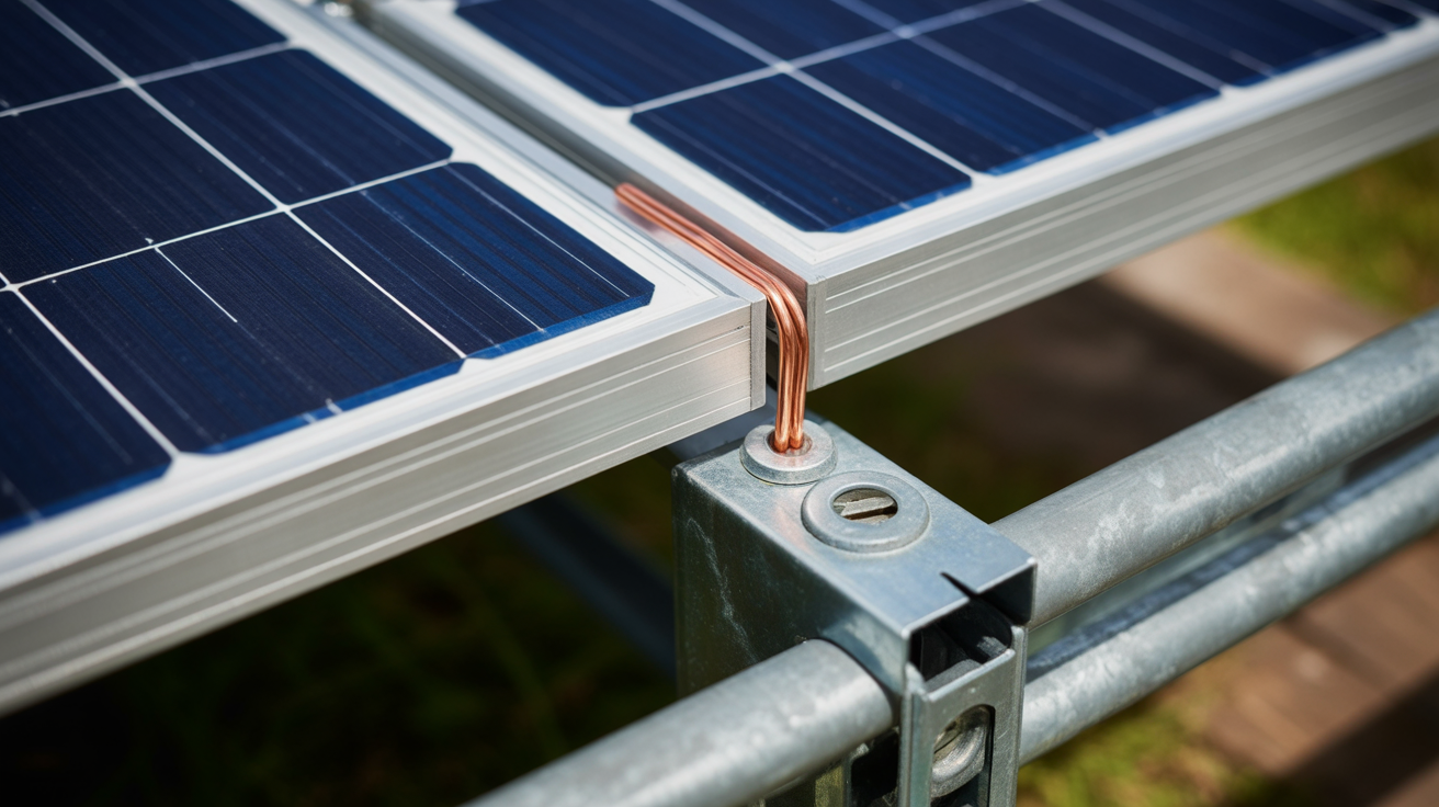
Regardless of system grounding topology, equipment grounding is non-negotiable. It ensures that all metallic components that could become energized during a fault—such as module frames, racking, and inverter chassis—are safely bonded together and connected to the earth.

Bonding and the Equipment Grounding Conductor (NEC)
The NEC is extremely specific about bonding. It requires a continuous, unbroken path for the EGC from the furthest module all the way back to the main grounding point. This often involves using specialized bonding hardware for racking systems and ensuring that all connections are secure and corrosion-resistant. Common installation errors, such as relying on the anodized surface of a rack for continuity or using improperly sized lugs, can compromise this critical safety path. These mistakes can have severe consequences for system reliability, an issue detailed in 7 grounding mistakes that kill PV reliability under NEC/IEC. For installations in challenging environments, proven methods are essential: Stop mis-bonding racks: Proven PV earthing for harsh climates.
Protective Earth (PE) and Equipotential Bonding (IEC)
The IEC's goal with the Protective Earth (PE) conductor is similar: create an "equipotential zone." This means connecting all exposed conductive parts so that, during a fault, they all rise to the same potential. By doing so, there is no dangerous voltage difference between two pieces of equipment that a person might touch simultaneously. While the objective is the same as the NEC's EGC, the sizing calculations and connection requirements for the PE conductor can differ based on the specific IEC standard and system type (TN, TT, or IT).
Navigating Modern Challenges: RSD and Energy Storage
As solar and storage technology evolves, so do the safety standards governing them. New requirements add layers of complexity to grounding and earthing design.
How Rapid Shutdown (RSD) Influences Grounding (NEC)
In the U.S., NEC Article 690.12 mandates rapid shutdown capabilities for PV systems on buildings. This function is designed to protect firefighters by reducing the voltage of the DC conductors to a safe level. RSD components themselves must be properly grounded as part of the overall equipment grounding system. It's important to recognize that RSD is an additional layer of safety that works in concert with, not in place of, standard grounding practices. For more on this interaction, see Do rapid shutdown rules change earthing? NEC vs IEC answers.
Grounding for Energy Storage Systems (ESS)
Energy storage systems introduce their own grounding challenges, as they contain both a DC battery bank and an AC output from an inverter. The metal enclosure of the ESS, the battery racking, and the inverter chassis must all be bonded together and connected to the grounding system. With our integrated ESS solutions, we simplify this process. Our home energy storage systems are designed with pre-engineered grounding points, combining high-performance LiFePO4 batteries and hybrid inverters into a single unit. This thoughtful design helps ensure a reliable and safe installation that meets stringent code requirements. The complexity of these systems, especially in microgrids, requires careful planning, as outlined in this roadmap: Roadmap: Earthing microgrids with ESS to IEC and IEEE 142.
Practical Implications for Installers and System Designers
Successfully deploying systems globally requires a practical understanding of these standards and the ability to translate between them.
Designing for Compliance: A Unified Approach
The most critical step is to identify the governing standard for the project location at the very beginning of the design phase. A system designed for an IEC market will likely not meet NEC requirements without significant modification, and vice versa. This is especially true for equipment certification. For example, an inverter compliant with IEC standards may not be listed to the corresponding UL standards required in the U.S. This makes cross-border projects particularly challenging. You can find guidance on creating compliant designs here: How to design compliant PV/ESS earthing across NEC and IEC. Real-world examples, like this Case study: Converting IEC earthing to NEC for US rooftops, highlight the practical hurdles involved.
Testing and Verification
Installation isn't complete until the grounding system is verified. This involves performing continuity tests to ensure all bonded components have a solid connection and measuring the resistance of the grounding electrode to the earth. Specialized tools are needed for these measurements, and using them correctly is key to confirming compliance and ensuring safety. A review of available equipment can help you choose the right tools for the job: Tool review: Grounding testers for PV/ESS code compliance.
The ANERN Advantage in a Complex World
With years of dedicated experience in the solar and energy storage industry, we understand these global complexities. We focus on developing reliable and scalable energy solutions that help you achieve energy independence. Our products, from robust LiFePO4 batteries to complete off-grid solar solutions, are built with the installer in mind. We provide clear documentation and support to help you achieve a compliant and safe grounding installation, no matter the regulatory environment.
Building a Safer Energy Future
Ultimately, the differences between NEC and IEC grounding standards boil down to two distinct safety philosophies: the NEC's prescriptive focus on clearing faults rapidly and the IEC's performance-based approach to preventing dangerous touch voltages. Both paths lead to the same goal of a safe and reliable energy system. For any professional in the solar and storage sector, mastering these differences is not just about compliance; it's about a fundamental commitment to safety. By choosing high-quality components and adhering to sound engineering principles, we can build the dependable energy infrastructure of tomorrow.
Disclaimer: This article provides a general overview of grounding standards and is not a substitute for professional engineering advice or a thorough review of the applicable codes and standards for your specific location and project. Always consult with a qualified professional for your system design and installation.


Leave a comment
All comments are moderated before being published.
This site is protected by hCaptcha and the hCaptcha Privacy Policy and Terms of Service apply.