In the world of solar and energy storage systems, safety is the bedrock of every successful installation. A critical component of this safety framework is the proper grounding or earthing of electrical equipment. While the goal is universal—protecting people and property from electrical faults—the methods and terminology vary significantly across the globe. The two dominant standards are the National Electrical Code (NEC) in the United States and the International Electrotechnical Commission (IEC) standards used in Europe and many other regions. Understanding the distinctions between NEC equipment grounding and IEC protective earth is crucial for anyone working with global products or in different markets.
Foundational Concepts: What Are We Protecting Against?
Before comparing the standards, it's important to understand the fundamental purpose of these systems. They are designed to mitigate the risks of electric shock and fire by managing fault currents.
The Role of Grounding in Fault Protection
When an energized conductor accidentally touches a metal enclosure—be it an inverter chassis, solar panel frame, or conduit—a fault occurs. Without a proper path to ground, this enclosure becomes energized, posing a severe shock hazard. A grounding system provides a safe, low-resistance path for this fault current to flow. This high current surge is designed to quickly trip a circuit breaker or blow a fuse, de-energizing the circuit and eliminating the danger.
Terminology: Grounding vs. Earthing
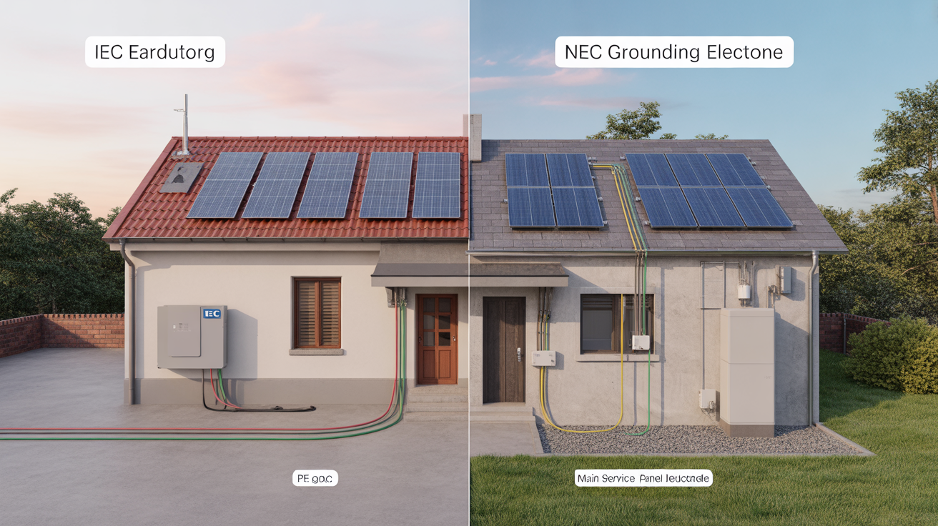
The terms themselves offer the first clue to the different approaches. In North America, the term "grounding" is used extensively. The NEC provides specific definitions for grounding conductors that connect equipment to the earth. Conversely, the IEC and most of the world use the term "earthing." A "protective earth" or PE conductor serves a similar function. While the concepts overlap, the implementation under each standard has important differences.
The NEC Approach: Equipment Grounding Conductor (EGC)
The NEC, specifically NFPA 70, takes a highly prescriptive approach to safety. The system is built around robust bonding and a single, clearly defined path for fault currents.
What is the Equipment Grounding Conductor?
The Equipment Grounding Conductor (EGC) is a core component of the NEC's safety system. It is a conductor or metallic pathway that connects all non-current-carrying metal parts of an electrical system. This includes everything from inverter casings and racking systems to junction boxes and conduits. The EGC's sole purpose is to provide a reliable, low-impedance path for fault current to travel from the fault location back to the power source.
System Grounding and the Neutral-Ground Bond
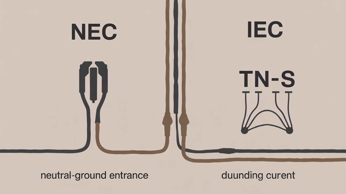
In a typical NEC-compliant system, the utility-supplied neutral conductor is intentionally connected to the grounding system at one single point: the service entrance. This connection, known as the main bonding jumper, is critical. When a fault occurs, the EGC carries the fault current back to this point, where it can then flow to the source transformer via the grounded neutral conductor, completing the circuit and tripping the overcurrent protection device.
Practical Application in Solar Installations
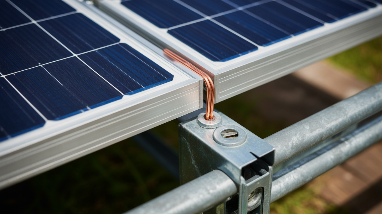
For solar energy systems, the EGC is a continuous network. It bonds the metal frames of all PV modules, the mounting racks, and the inverter chassis. This ensures that no part of the accessible metal structure can become dangerously energized. The NEC provides specific articles and calculations for correctly sizing the EGC based on the circuit's overcurrent protection, ensuring it can handle the potential fault current.
The IEC Approach: Protective Earth (PE)
The IEC standards, particularly the IEC 60364 series, offer more flexibility by defining several different earthing systems. The choice of system depends on the utility's infrastructure, the type of installation, and local regulations. As detailed in the IRENA report Grid Codes for Renewable Powered Systems, international standards like IEC 61140 are fundamental in defining common aspects for protection against electric shock.

Understanding the Protective Earth Conductor
The Protective Earth (PE) conductor in the IEC world serves the same primary purpose as the NEC's EGC: it connects all exposed conductive parts of equipment to the main earthing terminal. This ensures that in the event of a fault, these parts do not rise to a hazardous voltage.
IEC Earthing Systems (TT, TN, IT)
Unlike the NEC's singular approach, the IEC defines several system configurations:
- TN System: The letter 'T' stands for Terra (Earth), and 'N' for Neutral. In this system, the power source is directly connected to earth. Installations are connected to that same earth point via the PE conductor. This is the system most analogous to the NEC standard. It has sub-variants like TN-S (separate neutral and protective conductors) and TN-C (combined neutral and protective conductor).
- TT System: The power source has its own connection to earth, but the installation has a separate, independent connection to earth (a local earth electrode). The fault path is through the general mass of the earth, which has a higher impedance. This system often requires the use of Residual Current Devices (RCDs) for adequate protection.
- IT System: The power source is either isolated from earth or connected through a very high impedance. This system is typically used in sensitive applications like hospitals or industrial processes where continuity of service is critical, as a first fault does not cause a trip.
Key Differences and Practical Implications
Navigating between these standards requires more than just a terminology swap. The practical differences have major implications for equipment design, installation practices, and global product certification.
Conductor Identification and Sizing
Color codes are an immediate and obvious difference. The IEC strictly mandates a green-and-yellow striped conductor for the PE. The NEC allows for a green conductor, a green conductor with yellow stripes, or a bare copper conductor for the EGC. Sizing calculations also differ, as they are based on different tables and fault-clearing assumptions within each code.
Comparison Table
| Feature | NEC (National Electrical Code) | IEC (International Electrotechnical Commission) |
|---|---|---|
| Primary Terminology | Equipment Grounding | Protective Earth (PE) |
| Main Conductor | Equipment Grounding Conductor (EGC) | Protective Earth (PE) Conductor |
| Color Code | Green, Green with Yellow Stripe, or Bare Copper | Green with Yellow Stripe |
| System Approach | Focus on a single, solidly grounded system with a mandatory EGC path back to the source. | Defines multiple earthing systems (TN, TT, IT) based on the source and installation earthing arrangement. |
| Fault Current Path | Low-impedance path via the EGC to the main bonding jumper, designed for high fault currents to trip overcurrent devices quickly. | Varies by system. TN is similar to NEC. TT relies on a local earth electrode, often requiring RCDs due to higher impedance. |
| Primary Standard | NFPA 70 | IEC 60364 series, IEC 61140 |
Impact on Global Product Deployment
These differences are a critical consideration for manufacturers of solar inverters and energy storage systems. A product designed for the European market (IEC) may not be inherently compliant with NEC requirements. Its internal bonding, fault current handling capability, and grounding terminals must be evaluated and often certified specifically for the North American market. As the IEA notes in its reports, such as Getting Wind and Solar onto the Grid, aligning distributed energy resources with local grid infrastructure and regulations is essential for successful deployment.
Bridging the Gap for Safe Installations
While the philosophies of NEC and IEC differ, both are rigorously developed to ensure safety. The key takeaway is that an installer or system designer must adhere strictly to the code adopted in their specific jurisdiction. You cannot mix principles from both. For grid-tied renewable energy systems, interconnection standards like IEEE 1547 in the US and EN 50549 in Europe build upon these foundational grounding requirements to ensure safe interaction with the utility grid. Ultimately, a deep understanding of the applicable code is non-negotiable for a safe, reliable, and compliant energy system.
Disclaimer: This information is for educational purposes only and does not constitute professional engineering or installation advice. Always consult a qualified professional and adhere to all local codes and regulations.
Frequently Asked Questions
Can I use the terms "grounding" and "earthing" interchangeably?
While they refer to the same safety concept, it is best to use the term specific to the standard you are working with to avoid confusion. Use "grounding" for NEC contexts and "earthing" for IEC contexts to maintain clarity with inspectors, engineers, and suppliers.
Why does the NEC allow a bare copper wire for grounding?
A bare conductor is permitted for the EGC because it is not intended to carry current under normal operating conditions. Its visibility also helps installers and inspectors quickly identify it as a grounding conductor and ensure it is not mistaken for a neutral or phase conductor.
What is the biggest challenge when adapting an IEC-compliant product for the US market?
The primary challenge is ensuring the equipment's internal bonding and grounding scheme meets the NEC's stringent requirements. This often involves verifying or creating a suitable bonding point for the EGC and ensuring the system's fault current path is compatible with US overcurrent protection practices, which rely on high fault currents for rapid tripping.


Leave a comment
All comments are moderated before being published.
This site is protected by hCaptcha and the hCaptcha Privacy Policy and Terms of Service apply.