
Properly sizing the conductors in a solar and energy storage system is about much more than just connecting components. It's a critical step that directly impacts safety, performance, and the long-term return on your investment. An incorrectly sized wire can lead to lost energy, create safety hazards, and even cause system shutdowns. Achieving energy independence relies on a well-designed system, and that starts with the right foundation—the wiring.
This guide provides a thorough overview of conductor sizing and voltage drop. We will cover the core principles, calculation methods, and practical applications for solar PV and energy storage systems (ESS). Understanding these concepts ensures your system, whether it’s an off-grid solar solution or a home energy storage system, operates at its full potential.
The Fundamentals of Conductor Sizing
Before calculating voltage drop, you must first select a conductor that can safely handle the electrical current. This involves understanding ampacity, material properties, and environmental conditions.
What is Ampacity?
Ampacity is the maximum current, in amperes, that a conductor can carry continuously without exceeding its temperature rating. Think of it as the electrical equivalent of a pipe's diameter determining how much water can flow through it. Pushing too much current through a small wire generates excessive heat, which can melt the insulation and create a fire hazard.
Several factors influence a conductor's ampacity:
- Wire Gauge: In the American Wire Gauge (AWG) system, a lower number indicates a thicker wire with higher ampacity.
- Insulation Type: The material surrounding the metal conductor has a specific temperature rating (e.g., 75°C or 90°C). Higher-rated insulation allows for higher ampacity.
- Ambient Temperature: Wires installed in hot environments, like on a rooftop, cannot dissipate heat as effectively. Their ampacity must be adjusted downwards.
- Conduit Fill: When multiple current-carrying conductors are bundled in a conduit, their collective heat reduces the ampacity of each wire.
National and international standards, such as the National Electrical Code (NEC) in the United States, provide detailed tables for determining ampacity based on these conditions. For a deeper look into these regulations, see NEC/IEC Rules for Voltage Drop and Solar Conductor Sizing.
Choosing the Right Conductor Material
The two primary materials used for electrical conductors are copper and aluminum. Each has distinct properties that make it suitable for different applications.
Copper is the preferred choice for most solar applications due to its superior conductivity and durability. Aluminum is lighter and typically less expensive, but it is less conductive, meaning a larger gauge wire is needed to carry the same current as a copper one.
| Property | Copper | Aluminum |
|---|---|---|
| Conductivity | Higher (Lower resistance) | Lower (approx. 61% of copper) |
| Cost | Higher | Lower |
| Weight | Heavier | Lighter |
| Installation | More flexible, less prone to oxidation | Requires larger wire sizes, special anti-oxidant compound at connections |
While copper is often superior, aluminum can be a cost-effective option for long-distance feeder lines if sized correctly. To learn more about the trade-offs, explore Copper vs Aluminum: Cost, Ampacity and Drop in Long Runs and Will Aluminum Cables Meet PV Voltage Drop Limits?.
Understanding and Calculating Voltage Drop
Once you have a conductor sized for ampacity, the next step is to verify it meets voltage drop requirements. This is where system performance is truly optimized.
What is Voltage Drop and Why Does It Matter?
Voltage drop is the reduction of electrical pressure (voltage) along the length of a wire. It's a natural result of a conductor's resistance. A simple analogy is the pressure loss in a long garden hose—the pressure at the nozzle is always lower than at the spigot. In an electrical circuit, this loss means less power reaches your equipment.
Excessive voltage drop can cause serious problems:
- Reduced Power Output: Less voltage delivered from your solar panels to your inverter means less energy is converted, lowering your system's overall efficiency.
- Inefficient Battery Charging: In an energy storage system, significant voltage drop can prevent LiFePO4 batteries from reaching a full state of charge, impacting their lifespan and performance.
- Equipment Malfunction: Inverters and other electronics are designed to operate within a specific voltage range. Too much drop can cause them to underperform or shut down completely.
These issues can lead to frustrating system faults. Find out about common mistakes in 7 Conductor Sizing Mistakes That Nuisance-Trip Inverters.
The Voltage Drop Formula
Voltage drop is calculated using Ohm's Law (V = I × R). For practical circuit calculations, a more detailed formula is used:
For DC Circuits: VD = (2 × L × R × I) / 1000
Where:
- VD = Voltage Drop (in volts)
- L = One-way length of the circuit (in feet)
- R = Conductor resistance in ohms per 1,000 feet (from NEC Chapter 9, Table 8)
- I = Current (in amperes)
The "2" accounts for the round-trip distance the current travels. After calculating the voltage drop, you can find the percentage drop by dividing it by the source voltage (VD % = (VD / V_source) × 100). While manual calculations are useful, for complex systems, it's often best to use specialized software. You can find recommendations in our Tool Review: Best Voltage Drop Calculators for Solar+ESS.
Acceptable Voltage Drop Limits
While the NEC does not set mandatory voltage drop limits, it provides recommendations for system efficiency. A common industry standard is to keep voltage drop below 3% for the entire circuit from the power source to the load. For solar and storage systems, it's often broken down further:
| Circuit Path | Recommended Max Voltage Drop |
|---|---|
| PV Array to Combiner Box/Inverter | 1-2% |
| Battery Bank to Inverter | 1-2% |
| Inverter to AC Load Panel | 1-2% |
Sticking to these limits ensures that all components, from our high-performance solar inverters to our reliable LiFePO4 batteries, receive the voltage they need to operate correctly. For a complete breakdown, consult Voltage Drop Limits in Solar+Storage: The Ultimate Guide.
Practical Application in Solar and Storage Systems
Applying these principles correctly is what separates a mediocre system from a high-performing, reliable one. Let's look at the most critical wiring runs in a typical solar and storage installation.
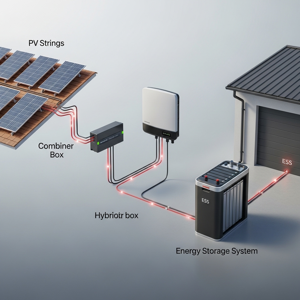
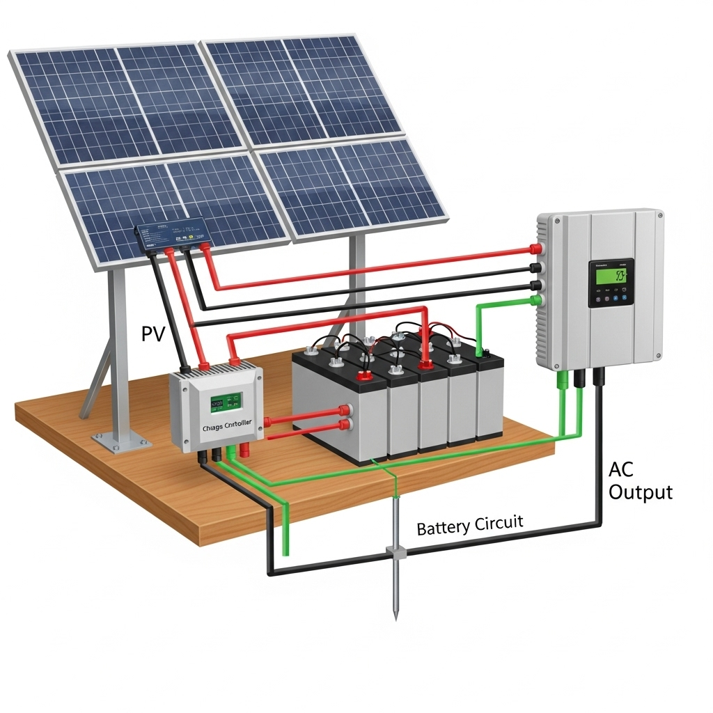
Sizing Conductors from PV Array to Inverter
The wires running from your solar panels carry the total energy your system generates. Sizing them correctly is the first step to minimizing power loss. You must calculate the maximum current from the panels and the total circuit length to select a wire gauge that keeps voltage drop within the recommended 1-2% range. This ensures your inverter receives maximum power, which is vital for the efficiency of our integrated home energy storage systems. For a step-by-step walkthrough, read How to Size PV and ESS Conductors to Tame Voltage Drop.
The Critical Link: Battery to Inverter Wiring
In any system with energy storage, the connection between the battery bank and the inverter is arguably the most important. This circuit handles very high currents, especially during high-power demand in an off-grid solar application. Even a small amount of resistance here can cause a significant voltage drop, leading to inverter shutdowns and inefficient battery performance.
Maximizing the performance of a high-quality LiFePO4 battery bank depends on minimizing these losses. As detailed in the ultimate reference for solar and storage performance, every percentage point of voltage drop in the battery-to-inverter connection can impact your system's round-trip efficiency and overall return on investment. This is why designing for minimal voltage drop is so important. Learn more at Stop Ignoring Voltage Drop in ESS Wiring—Design for ROI.
Common Mistakes and How to Avoid Them
Even experienced installers can make mistakes. Some common errors include forgetting to adjust ampacity for high temperatures, miscalculating the total circuit length, or sizing a wire based only on ampacity while ignoring voltage drop. These oversights can lead to underperforming systems and nuisance tripping. A real-world example of troubleshooting these issues can be found in our Case Study: Fixing DC Voltage Drop on a Remote PV Microgrid. It's also a common misconception that simply using a thicker cable is always the best solution, a topic explored in Myth vs Reality: Thicker Cables Don’t Always Cut Drop.
Building a Resilient System
Proper conductor sizing is not just a recommendation; it's a fundamental requirement for a safe, efficient, and reliable energy system. By carefully balancing ampacity requirements with voltage drop calculations, you ensure that every component, from the solar panels to the batteries and inverter, performs as intended. This attention to detail is the bedrock of a scalable energy solution that helps you achieve true energy independence.
A resilient system is built on careful planning and quality components. By understanding and applying the principles of conductor sizing, you are investing in the long-term health and performance of your solar and energy storage system.
Disclaimer: This article is for informational purposes only. It is not intended as professional electrical or financial advice. Always consult with a qualified electrician and adhere to all local codes and regulations when designing and installing any electrical system.
Leave a comment
All comments are moderated before being published.
This site is protected by hCaptcha and the hCaptcha Privacy Policy and Terms of Service apply.