As microgrids integrated with Energy Storage Systems (ESS) become more central to our energy infrastructure, the topic of proper earthing moves to the forefront. A correctly designed earthing system is not just a regulatory hurdle; it is the fundamental backbone of a safe, reliable, and resilient power system. Navigating the different international standards, primarily the IEC series and IEEE 142, requires a clear and systematic approach. This roadmap provides a framework for designing a compliant earthing system that ensures both personnel safety and operational stability for your microgrid.
Foundational Principles: Why Earthing is Critical in Microgrids
Before comparing standards, it is vital to appreciate the core functions of an earthing system within a microgrid. Its role extends far beyond simply connecting a wire to the ground. A well-executed earthing strategy is a critical investment in the longevity and safety of the entire installation.
Protecting Personnel and Equipment
The primary function of earthing is safety. It creates a low-impedance path for fault currents to flow to the earth, which causes protective devices like circuit breakers or fuses to operate quickly. This rapid disconnection minimizes the risk of electric shock to personnel who might come into contact with energized components. Furthermore, it protects sensitive and expensive equipment, such as inverters and battery systems, from damage caused by overvoltages from lightning strikes or utility switching events.
Ensuring System Stability and Reliability
In a microgrid, a stable voltage reference is paramount. The earthing system provides this reference, ensuring that control systems and power electronics operate as intended. Without a solid ground reference, inverters can struggle to synchronize, and measurements can become unreliable, leading to system instability. A proper earthing arrangement also helps to mitigate electromagnetic interference (EMI), which can disrupt communication and control signals within the microgrid.

Navigating the Standards: A Comparative Look at IEC and IEEE 142
The International Electrotechnical Commission (IEC) and the Institute of Electrical and Electronics Engineers (IEEE) provide the two most widely recognized sets of guidelines for earthing. While their goals are similar, their philosophies and terminologies differ significantly. Understanding these differences is the first step in the earthing design roadmap.
Core Philosophies and Terminology
IEEE Standard 142, often called the "Green Book," is a recommended practice focused on the grounding of industrial and commercial power systems, with a strong emphasis on managing fault currents to ensure system reliability and protect equipment. In contrast, the IEC standards, particularly IEC 60364 and IEC 61140, prioritize the protection of individuals from electric shock. This is achieved through different system earthing arrangements known as TN, TT, and IT. As noted in IRENA's report, Grid Codes for Renewable Powered Systems, the coordination between such international standards and local grid codes is an important point for successful system integration.
Key Technical Differences in Application
The choice between standards often depends on the project's geographical location and the specific requirements of the application. The following table provides a high-level comparison of their approaches.
| Feature | IEEE 142 (Recommended Practice) | IEC Standards (e.g., 60364) |
|---|---|---|
| Primary Focus | System reliability, fault clearance, equipment protection | Personnel safety (protection against electric shock) |
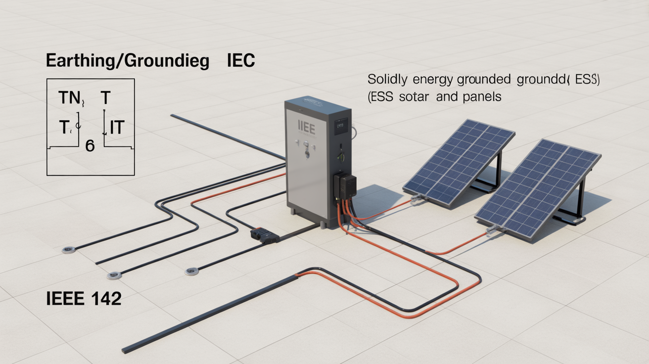
| System Types | Solidly grounded, ungrounded, high-resistance grounded, low-resistance grounded | TN (TN-S, TN-C, TN-C-S), TT, IT |
| Terminology | Grounding, Grounding Electrode Conductor (GEC), Equipment Grounding Conductor (EGC) | Earthing, Protective Earth (PE), Functional Earth (FE) |
| Application Scope | Primarily North American industrial and commercial systems | Global standard with regional adoptions and variations |
A Step-by-Step Roadmap for Compliant Microgrid Earthing
A structured approach simplifies the process of designing a compliant and effective earthing system for a microgrid with an ESS.
Step 1: System Characterization and Risk Assessment
First, you must thoroughly analyze the microgrid's architecture. Define its operational modes, particularly the distinction between grid-connected and islanded (stand-alone) operation. Identify all power sources, including the ESS, solar PV arrays, and any backup generators. Conduct a risk assessment to determine potential electrical hazards, calculating prospective fault current levels and identifying potential touch and step voltage risks for personnel.
Step 2: Selecting the Appropriate Earthing Topology
Based on your assessment, you can select the most suitable earthing system. For an IEC-compliant design, this involves choosing between TN, TT, or IT systems. For an IEEE-guided design, you would decide between solidly grounded or resistance-grounded methods. In many ESS applications, a resistance-grounded system is preferred in island mode because it limits fault currents, preventing damage to sensitive inverter components while still allowing for fault detection. The IRENA publication Quality infrastructure for smart mini-grids emphasizes that microgrids must comply with established safety and design standards, such as IEEE 1547, which governs interconnection.
Step 3: Design and Implementation
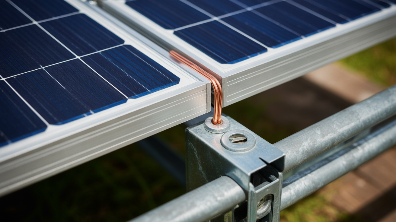
This phase involves the physical specification of the earthing system. You will select and size the grounding electrodes (such as ground rods, mats, or rings), the earthing conductors, and all bonding connections. A critical design consideration for a microgrid is establishing a single point of ground reference during islanded operation. This practice, often called a neutral-earth bond, prevents problematic ground loops and ensures a stable voltage reference for the entire system.
Addressing Specific Challenges in ESS Earthing
Integrating an ESS into a microgrid introduces unique earthing challenges that differ from traditional power systems. These require special attention during the design phase.
Island Mode vs. Grid-Connected Operation
The earthing system must be dynamic. When connected to the grid, the microgrid typically relies on the utility's ground reference. However, upon transitioning to island mode, that connection is lost. The microgrid's power conversion system (typically the ESS inverter) must then create a new, local ground reference. This is usually accomplished with an automatic transfer switch that establishes a neutral-to-ground bond within the microgrid's distribution panel.
Inverter Technology and Fault Current Behavior
Unlike traditional generators that can produce very high fault currents, battery inverters are power electronic devices and are typically current-limited. Their fault current contribution is often only slightly higher than their normal full-load rating. This characteristic must be factored into the design of the protection system. Fuses and circuit breakers must be sized and specified to operate correctly at these lower fault current levels to ensure the system is adequately protected.
Your Path to a Safe and Resilient System
Developing a robust earthing system for a microgrid with energy storage is a foundational step toward achieving energy independence. By following a structured roadmap, you can effectively navigate the complexities of IEC and IEEE 142 standards. The process begins with a thorough system assessment, moves to a careful selection of an appropriate earthing topology, and concludes with a detailed design that accounts for the unique operational modes of an ESS. This diligent approach ensures the final system is not only compliant but also fundamentally safe and reliable for years to come.
Frequently Asked Questions
Can I use an IT system for a microgrid with an ESS?
Yes, an IT (unearthed) system can be used. It offers high service continuity by not tripping on the first fault. However, it requires continuous insulation monitoring and a system to locate faults quickly. It is often used in critical facilities where shutdown is undesirable.
How does the earthing change when the microgrid switches to island mode?
When islanded, the connection to the utility's ground is lost. The microgrid must create its own local ground reference. This is typically achieved by switching a neutral-ground bond at the main inverter or a dedicated grounding transformer. This ensures a stable reference for the system's voltage and allows fault detection devices to operate correctly.
What is the main difference between 'earthing' (IEC) and 'grounding' (IEEE)?
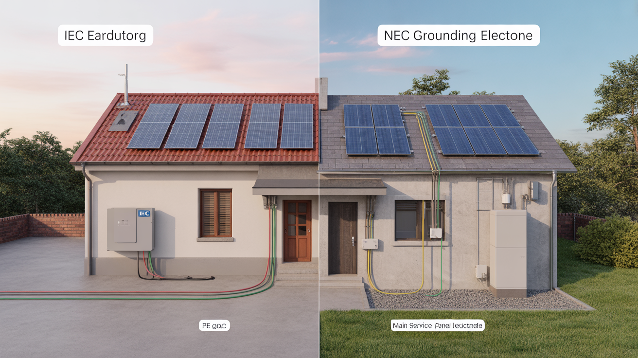
While often used interchangeably, 'earthing' in the IEC context primarily refers to connecting exposed conductive parts to the earth for shock protection. 'Grounding' in the IEEE/NEC context is broader, encompassing both safety (connecting to earth) and establishing a current return path for the electrical system (connecting the neutral). The core goals of safety and functionality are similar.


Leave a comment
All comments are moderated before being published.
This site is protected by hCaptcha and the hCaptcha Privacy Policy and Terms of Service apply.