The peak efficiency rating on a power converter's datasheet is an important number, but it only tells part of the story. Real-world performance depends on the entire efficiency curve—a map of how well the device converts power under various conditions. Ignoring the nuances of this curve leads to common but critical mistakes that can silently degrade your energy system by increasing Total Harmonic Distortion (THD) and exposing it to unnecessary surge stress.
Understanding these errors is the first step toward building a more resilient, reliable, and truly efficient power system. Let's examine five of the most common oversights and how to avoid them.
1. Mistaking Peak Efficiency for Constant Performance
It's easy to fixate on the 98% or 99% peak efficiency number. However, most energy systems rarely operate at the specific load that achieves this peak. This disconnect between datasheet perfection and reality is a primary source of inefficiency and stress.
The Reality of Part-Load Operation
Your system's load fluctuates throughout the day. Solar production wanes, and appliances cycle on and off. Operating at light loads is far more common than operating at full capacity. Many converters that boast high peak efficiency suffer a significant drop in performance at 10-30% of their rated capacity. This is a critical detail because, as studies on energy performance show, part-load operation is where many systems spend most of their time. Poor part-load efficiency means more energy is wasted as heat, directly impacting your return on investment.
Impact on THD at Low Loads
Total Harmonic Distortion is a measure of the 'noise' or distortion a power converter introduces into the AC waveform. The rapid switching of internal components, necessary for converting DC to AC, is the primary cause of these harmonics. While modern inverters are designed to minimize this, their effectiveness can wane at low loads. When an inverter optimized for peak power operates at a fraction of its capacity, the switching process can become less refined, leading to a higher THD percentage. According to standards like IEEE 519, maintaining low THD is crucial for power quality and preventing damage to connected devices.
Consequence for Surge Handling
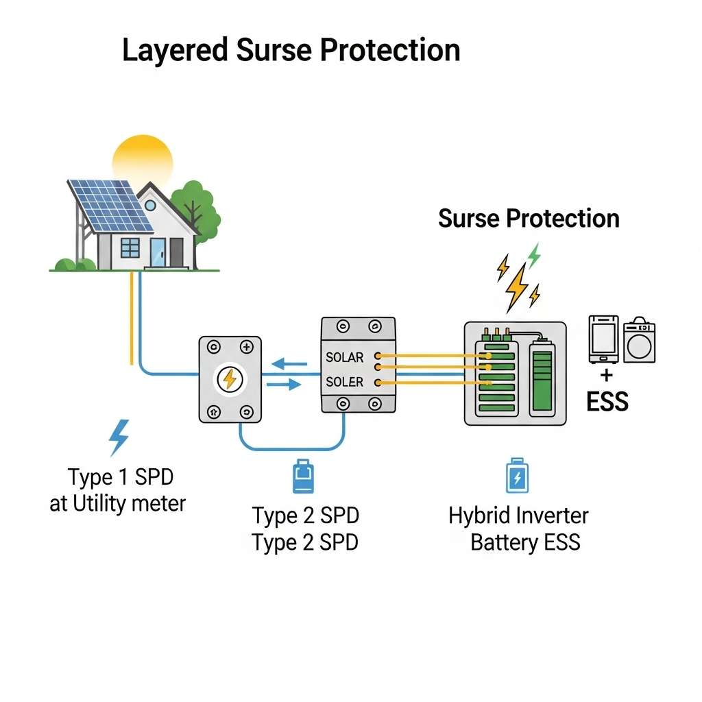
A system designed solely around a single peak efficiency point may lack the robustness to handle sudden changes in load, known as surges. When a large appliance like an air conditioner or pump starts, it creates a momentary, high-demand surge. An inverter operating in a less-efficient, low-load state may struggle to respond instantly, leading to voltage sags or spikes that stress both the inverter and the appliance.
2. Ignoring 'No-Load' Power Consumption
What happens when your system isn't powering any active loads? The inverter is still on, waiting. The energy it consumes in this standby state is called no-load or idle power consumption, and it's a significant factor in overall system efficiency.
The Silent Energy Drain
No-load consumption can range from a few watts to over 30 watts, depending on the inverter's design and size. While this may seem small, it adds up. An inverter drawing 25 watts continuously wastes 600 watt-hours per day, or over 219 kWh per year—energy that drains your batteries without doing any useful work. This constant drain is a parasitic loss that directly undermines your energy independence.
How It Skews the Real-World Efficiency Curve
A high no-load draw effectively flattens the low end of the efficiency curve, making the system highly inefficient for powering small, continuous loads like routers, security systems, or smoke detectors. If your daily energy profile includes long periods of low activity, a high idle draw can drastically lower your system's average 24-hour efficiency, regardless of its impressive peak rating.

3. Overlooking the Impact of Input Voltage Range
An inverter's efficiency is not only dependent on the output load but also on the input DC voltage from your solar array or battery bank. Operating outside the optimal voltage window can compromise performance and stability.
Efficiency Varies with Voltage
Power converters are engineered to perform best within a specific input voltage 'sweet spot'. As the input voltage drifts toward the upper or lower limits of the acceptable range, conversion efficiency typically declines. For example, a 48V inverter might achieve its highest efficiency at 52V but become progressively less efficient as the battery discharges down to 44V. This variation can be as much as a few percentage points, which is a significant factor in annual energy production.
Voltage Fluctuations and THD
Operating at the edges of the voltage range can also affect the stability of the inverter's internal electronics, potentially increasing Total Harmonic Distortion. A stable DC input allows the inverter's control algorithms to maintain a clean, sinusoidal AC output more effectively. Frequent or wide voltage swings force the inverter to work harder, which can introduce waveform imperfections.
4. Neglecting Temperature Derating Effects
Electronic components are sensitive to heat. As an inverter works to convert power, it generates its own heat due to internal losses. High ambient temperatures further compound this issue, leading to a process known as thermal derating.
Heat: The Enemy of Efficiency
Derating is the intentional reduction of a component's performance to prevent heat-related damage. Every power converter has a derating curve in its datasheet that shows how much its maximum power output must be reduced as the ambient temperature rises above a certain point (e.g., 25°C or 40°C). Ignoring this means you might not get the power you expect on a hot day, precisely when solar production and energy demand (for cooling) are at their highest.
Thermal Stress and Component Lifespan
Consistently operating at high temperatures places significant stress on internal components like capacitors and semiconductors, accelerating their degradation. This thermal stress not only reduces the inverter's lifespan but also compromises its ability to handle power surges. Overheated components are more susceptible to failure when faced with a sudden, high-current demand.
5. Choosing the Wrong Converter for the Application
Not all inverters are created equal, and selecting one based solely on its peak power rating is a common mistake. The shape of the efficiency curve should align with your specific load profile for optimal performance.
Matching the Curve to the Load Profile
Consider two different applications: an off-grid cabin with intermittent, heavy loads (water pump, power tools) and a grid-tied home with a constant, low-level base load (refrigeration, electronics). The cabin requires an inverter with excellent surge handling and strong peak power performance. The home, however, would benefit more from an inverter with a flat efficiency curve and very low no-load consumption to minimize waste during periods of low activity. Choosing an inverter with an efficiency profile that doesn't match the load profile is a recipe for inefficiency.
A Tale of Two Inverters
The table below illustrates why looking beyond peak efficiency is crucial.
| Metric | Inverter A | Inverter B |
|---|---|---|
| Peak Efficiency | 98.5% | 97.5% |
| Efficiency at 25% Load | 88% | 95% |
| No-Load Consumption | 30W | 5W |
| THD at 25% Load | <8% | <3% |
While Inverter A looks superior on paper with its higher peak efficiency, Inverter B is the clear winner for applications with significant part-load or standby periods. Its flatter efficiency curve, lower idle consumption, and better THD performance at low loads make it a more robust and efficient choice for most real-world scenarios.
Achieving True System Resilience
Avoiding these five mistakes moves you beyond chasing a single specification and toward a holistic understanding of power conversion. A truly efficient and reliable energy system depends on selecting a converter whose entire performance profile—across different loads, voltages, and temperatures—matches your unique needs. By scrutinizing the full efficiency curve, you can minimize THD, improve surge stress handling, and ensure your system delivers on its promise of dependable, clean energy for years to come. For a more detailed look at key metrics that define system robustness, the ultimate reference on solar storage performance offers valuable insights.
Frequently Asked Questions
What is Total Harmonic Distortion (THD)?
Total Harmonic Distortion (THD) is a measurement that quantifies the extent to which a waveform deviates from a pure sine wave. In power systems, it's caused by the switching of electronic devices like inverters. High THD can lead to reduced efficiency, overheating of equipment, and operational problems for sensitive electronics.
How does part-load efficiency affect my energy system?
Part-load efficiency is critical because most systems rarely operate at 100% capacity. They spend a significant amount of time in low to medium power states. If an inverter has poor efficiency at these lower loads, it will consistently waste a larger portion of your generated or stored energy as heat, reducing the overall effectiveness of your solar and storage investment.
Can improving efficiency also improve surge handling?
Yes, there's a strong connection. A more efficient system generates less waste heat, which means components operate at lower temperatures. Cooler, less-stressed components are better able to manage the sudden electrical and thermal demands of a power surge. Therefore, selecting a converter with a flat, high-efficiency curve contributes directly to its durability and its ability to handle large, sudden loads without faltering.


Leave a comment
All comments are moderated before being published.
This site is protected by hCaptcha and the hCaptcha Privacy Policy and Terms of Service apply.