Choosing between a fixed-tilt and a single-axis tracker for a solar project often centers on energy yield and financial returns. While trackers consistently produce more energy, that performance advantage introduces significant structural complexities. A deeper analysis of how each system handles environmental forces, specifically through their load paths and susceptibility to torsion, is critical for ensuring long-term asset safety and reliability. The structural integrity of the mounting system is the foundation of any successful solar installation.
Understanding Load Paths in Fixed-Tilt Systems
A load path is the journey a force takes through a structure until it is safely dissipated into the ground. In fixed-tilt solar racking, this path is straightforward and static. The rigid, unchanging geometry of the system creates a predictable response to external pressures like wind and snow.
Direct and Predictable Force Distribution
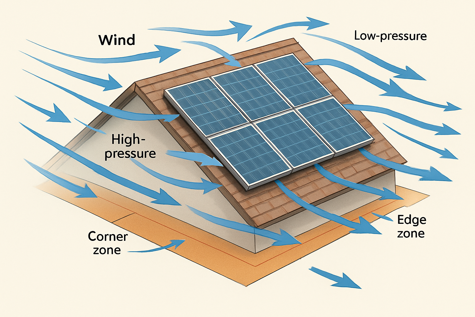
For a fixed-tilt array, forces are transferred directly from the solar modules to the mounting rails. From the rails, these loads move through the support posts and into the foundations. Because the tilt angle never changes, the way the structure resists uplift from wind or downward pressure from snow is constant. This predictability simplifies the engineering analysis, allowing for precise calculations of stress at key connection points without accounting for dynamic variables.
Key Stress Points and Failure Modes
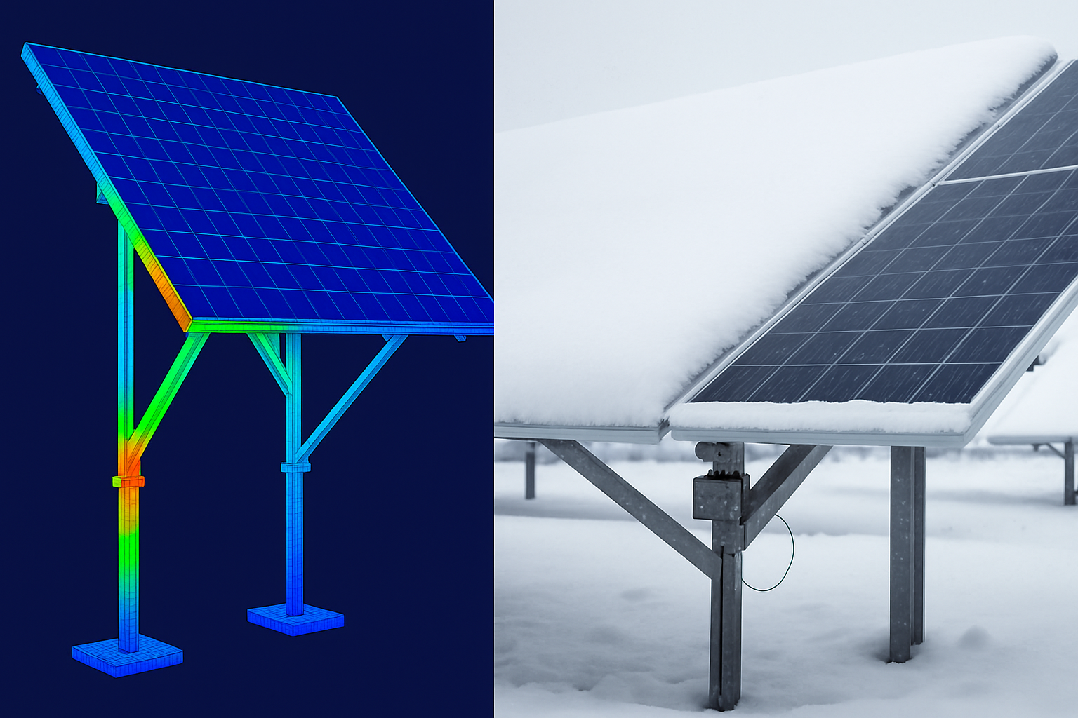
The primary stress points in fixed-tilt systems are the connections between the rails and posts, as well as the foundation's resistance to uplift and shear forces. Under extreme wind, the most common failure mode is the entire array being lifted if the foundations are not adequately designed. Heavy, uniform snow load, on the other hand, can cause rails to bend or fail if their span is too great for the specified load. The design focuses on pure strength and rigidity to counter these well-understood forces.
The Dynamic Challenge of Tracker Load Paths
Single-axis trackers fundamentally change the structural equation by introducing movement. As the array rotates to follow the sun, its orientation to wind and its method of handling loads change continuously. This dynamic nature creates complex forces that are not present in fixed-tilt designs.
The Critical Role of the Torque Tube
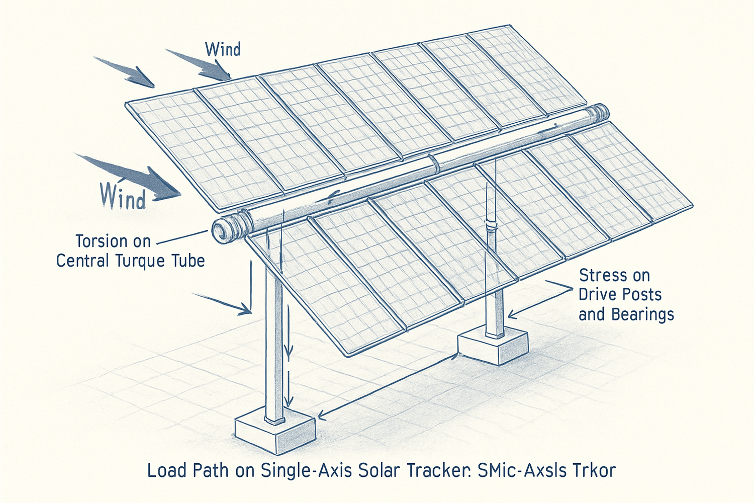
The backbone of a modern single-axis tracker is the torque tube. This component serves two purposes: it facilitates the rotation of the solar modules and acts as the primary structural member for transferring loads along the entire row. Instead of each small section of racking having its own direct path to the ground, loads are collected along the torque tube and concentrated at the foundation posts, which are spaced much farther apart than in fixed-tilt systems.
Torsional Forces: The Defining Risk Factor
Torsion is the single most important structural consideration separating trackers from fixed-tilt systems. This twisting force occurs when wind pressure is not applied uniformly across the face of the array. For example, wind striking the leading edge of a tilted tracker creates lift, while the trailing edge may experience less force. This imbalance creates a powerful rotational torque on the tube. The entire design of the tracker, from the thickness of the torque tube to the strength of the drive motor, is engineered to resist this twisting. Failure to manage torsion can lead to catastrophic structural failure.
Comparing Structural Risks: Wind and Snow Engineering
The decision to use trackers is often driven by their increased energy output. According to research like the Next Generation Wind and Solar Power report, single-axis trackers can boost electricity generation by 12-25% in high insolation areas. However, this gain requires managing a different and more complex set of structural risks.
Wind Load Dynamics and Torsional Instability
Trackers are more susceptible to complex aerodynamic phenomena. Their long, slender shape can behave like an airplane wing, making them vulnerable to forces like galloping (low-frequency, high-amplitude oscillations) and vortex shedding. A sudden high-speed gust can induce torsional instability faster than the tracker's control system can react and move the array to a safe stow position. This is why advanced engineering, including wind tunnel testing and the use of dampers, is standard for large-scale tracker projects. The push for Clean Energy Innovation includes developing smarter materials and control systems to handle these dynamic stresses more effectively.
Snow and Ice Accumulation Challenges
Snow presents a different challenge. While a fixed-tilt system experiences a relatively uniform downward load, snow can accumulate unevenly on a tracker. A partial melting and refreezing event can create an unbalanced load that induces a constant torsional strain on the torque tube. Furthermore, heavy ice buildup can seize the drive system, preventing the tracker from stowing properly during a wind event, leaving it vulnerable in a high-drag position.
Design and Mitigation Strategies
Both system types can be designed for resilience, but they require different engineering approaches. The focus for fixed-tilt is on brute strength, while for trackers, it is on a combination of strength, flexibility, and intelligent control.
Reinforcing Fixed-Tilt Structures
For fixed-tilt systems in high-wind or heavy-snow regions, the strategy is straightforward: increase the strength of the components. This includes using larger-gauge steel, shortening rail spans, adding structural bracing, and designing more robust foundations. The engineering is well-established and relies on proven static load calculations to ensure reliability.
Engineering Resilience in Trackers
Mitigating risk in trackers is a more multifaceted task. It involves designing larger, more robust torque tubes, incorporating damping mechanisms to absorb harmonic oscillations, and implementing smart, responsive control systems. These systems use anemometers to detect rising wind speeds and quickly command the tracker to move to a defensive stow position. Ensuring the long-term health of these complex systems also involves monitoring. Just as understanding solar storage performance is key to energy independence, monitoring structural feedback from trackers is crucial for preventing failures.
A Final Assessment
The choice between fixed-tilt and trackers involves a clear trade-off. Fixed-tilt systems offer structural simplicity and highly predictable performance under load, making them an inherently lower-risk choice from a purely structural standpoint. Their failure modes are well-understood and can be mitigated with sufficient material strength. Trackers, while offering superior energy production, introduce the complex and potent force of torsion. Their reliability hinges not just on material strength but also on the sophistication of their control systems and their ability to react to changing weather conditions. Ultimately, the higher upfront cost and engineering complexity of trackers must be weighed against their increased energy revenue and the specific environmental risks of a project site.
Frequently Asked Questions
What is torsion in a solar tracker?
Torsion is the twisting force experienced by the central torque tube of a tracker. It's caused by uneven pressure, typically from wind hitting the edges of the panel array at different intensities, creating a rotational load.
Are trackers less reliable than fixed-tilt systems?
Not necessarily, but they are more complex. Trackers have moving parts and face dynamic torsional loads that fixed systems do not. Their reliability depends heavily on the quality of engineering, robust components, and intelligent control systems for stowing during adverse weather.
How does a tracker's stow position help mitigate wind load?
The stow position, usually a near-flat or high-tilt angle, presents a smaller, more streamlined profile to the wind. This drastically reduces both lift and drag forces, minimizing stress on the structure and, most importantly, reducing the torsional load on the torque tube.


Leave a comment
All comments are moderated before being published.
This site is protected by hCaptcha and the hCaptcha Privacy Policy and Terms of Service apply.