Proper grounding is the foundation of a safe and reliable solar PV or energy storage system (ESS). It protects personnel from electrical shock and equipment from damage during fault conditions. But simply following a design diagram is not enough. Verifying that your grounding system performs as intended requires precise measurement. This review covers the essential grounding testers you need to ensure your PV and ESS projects meet stringent code compliance requirements.
Why Grounding Verification is Non-Negotiable
A grounding system is only effective if it provides a continuous, low-impedance path for fault currents. Visual checks alone can be deceptive, failing to identify loose connections, internal corrosion, or improper installation. Quantitative testing provides the hard data needed to confirm the integrity of your system.
Beyond Visual Inspection: The Need for Quantitative Data
A visual inspection might confirm that a grounding conductor is connected, but it cannot tell you the quality of that connection. High resistance at a connection point can impede fault current, delaying the response of protective devices like circuit breakers. This can lead to equipment damage or create dangerous touch voltages. Using a specialized tester gives you a precise resistance value, offering definitive proof of a safe and effective grounding path. This data is indispensable for commissioning reports, safety audits, and client handover documents.
The Role of Testers in Meeting Grid Code Requirements
Grid codes are the rules that govern how power generation sources connect to the electrical grid. Compliance is mandatory. According to an IEA report on integrating renewables, checking and certifying grid code compliance is a critical process. As part of this, Getting Wind and Solar onto the Grid highlights that certification is an important tool to ensure generators fulfill requirements before exporting power. Grounding performance is a key part of this certification. System operators rely on data from commissioning tests to grant permission to operate. Without verified test results from proper equipment, a project can face significant delays.
Types of Grounding Testers for Solar and Storage Applications
Different testing scenarios require different tools. Selecting the appropriate tester is crucial for obtaining accurate results. The main types include fall-of-potential testers, clamp-on testers, and low-resistance ohmmeters.
Fall-of-Potential Testers (3-Point and 4-Point)
The fall-of-potential method is a highly accurate technique for measuring the resistance of a grounding electrode system to the earth. It involves placing two auxiliary stakes in the soil at specific distances from the electrode under test. A known current is circulated between the outer stake and the ground electrode, and the resulting voltage drop is measured using the inner stake. This method is ideal for commissioning new sites to verify that ground rods or grids meet the design specifications before the system is energized.

Clamp-On Ground Resistance Testers
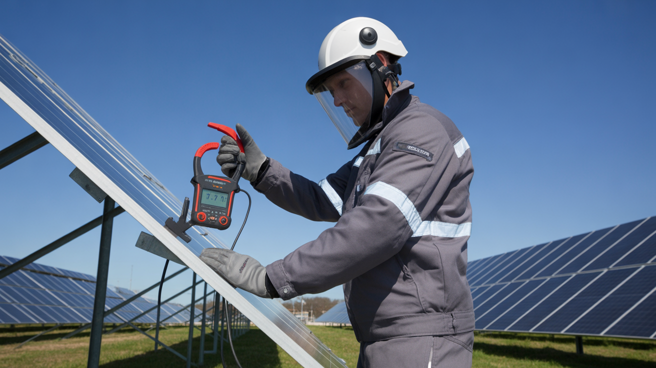
For existing systems, disconnecting the grounding system for testing is often impractical or unsafe. Clamp-on testers solve this problem. These instruments clamp around the grounding conductor and induce a small test current without requiring direct electrical contact. They measure the resistance of a complete grounding loop. This makes them exceptionally useful for routine maintenance, system audits, and troubleshooting. You can quickly test multiple points in an interconnected system to identify any degradation or faults that have developed over time.
Low Resistance Ohmmeters (DLROs)
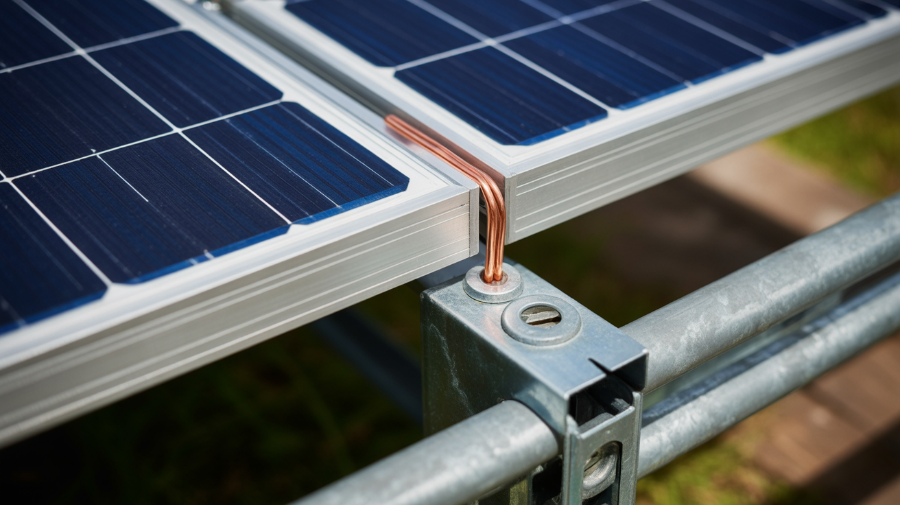
While fall-of-potential testers measure the connection to the earth, a Digital Low Resistance Ohmmeter (DLRO) verifies the integrity of the bonding connections above ground. A DLRO injects a DC current through a connection—such as between a solar module frame and the mounting rack—and measures the voltage drop to calculate resistance with micro-ohm precision. This is critical for ensuring that all metallic components are effectively bonded together, creating a continuous equipment grounding conductor (EGC) path as required by codes like the NEC.
Selecting the Right Tester for NEC and IEC Compliance
Choosing a tester involves more than just picking a type. You must consider its specifications and features to ensure it is suitable for the task and the environment. This decision directly impacts the safety and compliance of your solar PV grounding and energy storage system earthing.
Key Features to Look For
When evaluating grounding testers, consider these four critical features. First, check the measurement range and accuracy to ensure it can read the low resistance values typical of grounding systems. Second, good noise rejection is vital, as inverters and other power electronics can create electrical noise that interferes with readings. Third, verify the instrument's safety rating (e.g., CAT IV 600V) to ensure it protects the user from transients. Finally, data logging and reporting capabilities are essential for documenting compliance and creating professional reports for clients and authorities.
A Comparison of Tester Applications
To simplify your choice, this table summarizes the best applications for each tester type.
| Tester Type | Primary Use Case | Pros | Cons |
|---|---|---|---|
| Fall-of-Potential Tester | Commissioning new grounding electrode systems | Highly accurate; considered the definitive test method | Requires disconnection; needs access to soil for stakes |
| Clamp-On Tester | Maintenance and testing of existing, interconnected systems | Fast and easy to use; no disconnection needed | Measures entire loop resistance; less effective on isolated grounds |
| Low Resistance Ohmmeter (DLRO) | Verifying bonding connections and conductor continuity | Extremely precise for very low resistance values | Measures bonding, not the earth connection itself |
Practical Application: A Step-by-Step Testing Workflow
A structured testing workflow ensures all aspects of the grounding system are verified and documented. This process differs slightly between new installations and routine maintenance.
Commissioning a New PV Array
For a new installation, begin by using a fall-of-potential tester to confirm the grounding electrode system meets the required resistance value (e.g., 25 ohms or less per NEC guidelines, or as specified by the engineer). Next, use a DLRO to test all bonding connections point-to-point, from the module frames to the racking and back to the inverter chassis. This verifies the integrity of the equipment grounding path. Finally, document every measurement in a commissioning report, creating a baseline for future maintenance checks.
Annual Maintenance and Troubleshooting
During annual maintenance, a clamp-on tester is your most efficient tool. Use it to quickly check the ground loop resistance at key points, such as the main grounding electrode conductor and connections to inverters. Compare these readings to the baseline data from commissioning. If a measurement is high, it indicates potential degradation. You can then use a DLRO to investigate specific bonds in that part of the circuit to pinpoint the exact location of the high-resistance fault, such as a corroded lug or loose bolt.
Final Thoughts on Ensuring System Integrity
Grounding testers are fundamental tools for quality assurance in the solar and energy storage industries. They transform safety from a theoretical concept into a measurable, verifiable reality. Investing in the right equipment and implementing a rigorous testing protocol protects assets, ensures safety, and builds trust with clients and regulators. As technology and grid requirements evolve, the importance of robust compliance verification will only grow. As detailed in the IRENA report Grid Codes for Renewable Powered Systems, combining test strategies like type tests, on-site commissioning, and in-operation monitoring is the best way to achieve and maintain grid code compliance.
Frequently Asked Questions
What is a good ground resistance value for a solar PV system?
While the NEC often cites 25 ohms or less for a single electrode, the primary goal is a low-impedance path to clear faults. The specific value depends on the system design and local codes. The lower, the better. Always consult the relevant standards (NEC or IEC) and engineering specifications for your project.
Can I use a standard multimeter to test grounding?
No. A standard multimeter cannot accurately measure the low resistance values required for grounding and bonding verification. It also does not use the correct testing methods, like the fall-of-potential or clamp-on techniques, to measure the connection to the earth. Using the wrong tool can give you a false sense of security.
How often should grounding systems be tested?
Grounding systems should be thoroughly tested during commissioning. After that, periodic testing should be part of a regular maintenance schedule, typically annually. The frequency may increase in corrosive environments (like coastal areas) or after any modifications to the system.
Leave a comment
All comments are moderated before being published.
This site is protected by hCaptcha and the hCaptcha Privacy Policy and Terms of Service apply.