Proper grounding is the foundation of any safe and reliable solar photovoltaic (PV) or energy storage system (ESS). It protects equipment from damage and, more importantly, safeguards people from electrical shock. For professionals working in the global energy market, navigating the two dominant standards—the National Electrical Code (NEC) and the International Electrotechnical Commission (IEC)—can be complex. These standards approach grounding with fundamentally different philosophies, leading to distinct design and installation requirements.
Understanding these differences is not merely an academic exercise. It is a critical requirement for ensuring compliance, system longevity, and safety across international borders. This guide provides a clear, practical comparison of NEC and IEC grounding principles specifically for PV and storage applications.

Core Philosophies: Fault Clearance vs. Shock Prevention
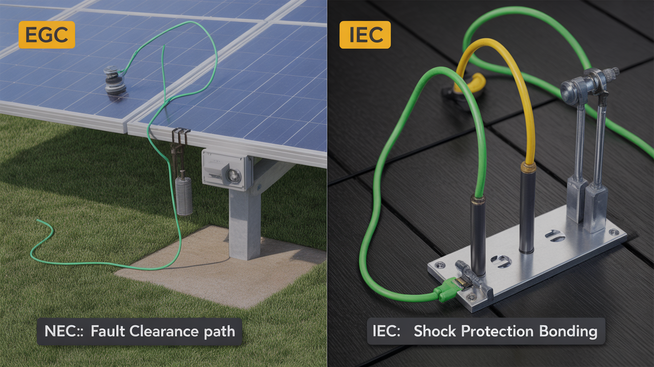
The primary distinction between NEC and IEC grounding lies in their ultimate safety objective. While both aim to prevent harm, they achieve it through different mechanisms.
The NEC Approach: Clearing Faults Quickly
The NEC, predominantly used in the United States, prioritizes rapid fault clearance. Its main goal is to create a low-impedance path for fault current to flow back to the source. This surge of current is designed to be high enough to instantaneously trip an overcurrent protection device (OCPD), such as a circuit breaker or fuse. By de-energizing the circuit almost instantly, the NEC system removes the hazard. The Equipment Grounding Conductor (EGC) is the key component in this system, acting as the dedicated pathway for this fault current.
The IEC Approach: Managing Touch Voltage
IEC standards, which are the basis for most national codes outside of North America, focus on managing touch voltage. The primary goal is to ensure that if a fault occurs, the voltage a person might come into contact with (touch voltage) remains below a safe threshold (typically 50V). This is achieved through various earthing systems (like TN, TT, and IT) that rely on equipotential bonding. The Protective Earth (PE) conductor connects all exposed metallic parts, ensuring they are at the same electrical potential. This method prioritizes human safety even if the fault persists for a short period before a protective device activates.
Key Terminology and Component Differences
While the concepts are similar, the language and components used by each standard differ significantly. Understanding this terminology is the first step to correct application.
Grounding vs. Earthing
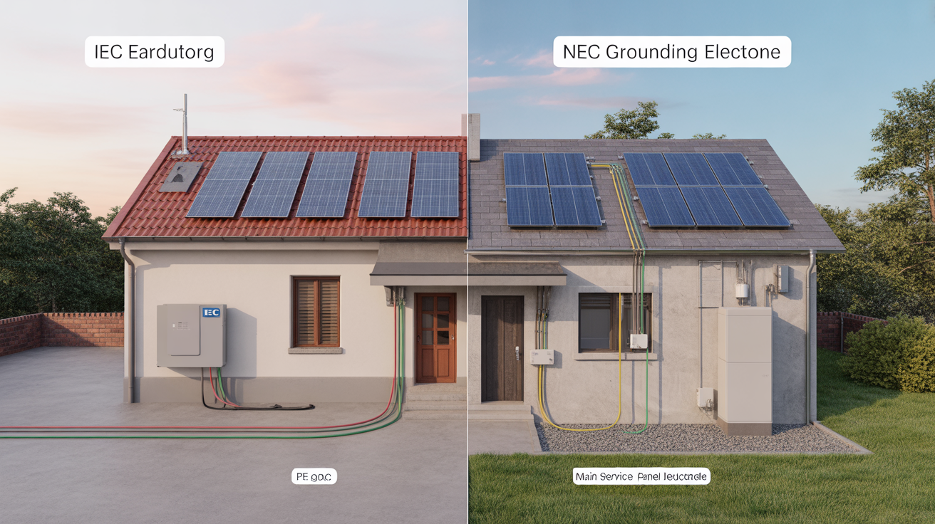
Though often used interchangeably, these terms have specific contexts. "Grounding" is the term used in the NEC, referring to the connection to the earth and the system of conductors that provides the fault current path. "Earthing" is the equivalent term used in IEC standards. The distinction is subtle but important for clear communication on international projects.
Conductors and Their Roles
The function of the protective conductor is central to both standards, but its designation and some aspects of its implementation differ.
- NEC Equipment Grounding Conductor (EGC): This conductor connects the non-current-carrying metal parts of equipment, raceways, and enclosures to the system's grounded conductor and the grounding electrode. Its primary job is to carry fault current.
- IEC Protective Earth (PE): This conductor serves a similar purpose, connecting exposed conductive parts of equipment to the main earthing terminal. Its role is primarily for protection against electric shock through bonding.
| Feature | NEC (National Electrical Code) | IEC (International Electrotechnical Commission) |
|---|---|---|
| Primary Philosophy | Fault Clearance | Shock Protection (Touch Voltage Management) |
| Key Conductor | Equipment Grounding Conductor (EGC) | Protective Earth (PE) |
| Main Goal | Provide a low-impedance path to trip an overcurrent device quickly. | Maintain equipotential bonding to limit voltage exposure to personnel. |
| System Grounding | Often requires grounding one current-carrying conductor (e.g., neutral). | Flexible; allows for various earthing systems (TN, TT, IT), including ungrounded systems. |
| Geographic Scope | Primarily United States and countries adopting its standards. | Widely adopted globally, especially in Europe, Asia, and other regions. |
| Terminology | Grounding | Earthing |
Practical Application in PV and Storage Systems
These philosophical differences translate into tangible requirements for solar and energy storage installations.
Grounding PV Arrays
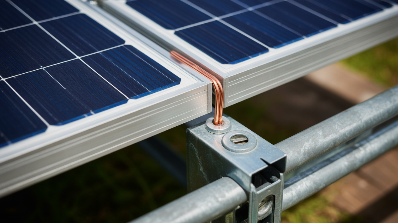
For PV systems, both standards require bonding all metallic components, including module frames and mounting racks, to create an electrically continuous path. However, the specifics diverge.
- NEC: Mandates that the EGC be sized to handle potential fault currents and requires specific listed and labeled components for bonding and grounding. The focus is on ensuring the path is robust enough to open a breaker.
- IEC: Focuses on ensuring the equipotential bonding is effective at preventing dangerous touch voltages. The sizing of the PE conductor is often linked to the phase conductors rather than a specific fault-current calculation.
As noted in the IEA's Technology Roadmap - Solar Photovoltaic Energy 2010, the rapid deployment of PV has created technical issues where standardized practices are essential for long-term safety and reliability.
Grounding Energy Storage Systems (ESS)
Energy storage adds another layer of complexity. The grounding of battery enclosures, inverter chassis, and associated hardware is critical. For DC-coupled systems, the grounding must accommodate both the PV and battery DC circuits. For AC-coupled systems, the grounding must integrate with the existing AC electrical system. The NEC provides specific articles covering ESS, while IEC compliance is typically achieved by adhering to a suite of standards covering batteries, inverters, and overall electrical installations.
Navigating Compliance in a Global Market
The rise of renewable energy is a global phenomenon. The World Energy Investment 2023 report highlights significant capital flowing into clean energy technologies worldwide. This global market presents challenges for manufacturers and installers who must adapt to different regulatory environments.
Challenges for International Projects
Designing a single product or system that is universally compliant is difficult. Key challenges include:
- Component Certification: Equipment must be tested and certified by a recognized body for the specific region of installation (e.g., UL for the U.S., CE for Europe).
- Conductor Sizing and Color Coding: Conductor sizes and insulation colors for grounding (green or bare for NEC EGC; green-and-yellow for IEC PE) must match local codes.
- System Design: A design based on an ungrounded (IT) system common under IEC rules would not be compliant in many NEC jurisdictions without significant modification.
As systems become more complex, integrating variable sources like solar and wind requires a deep understanding of the grid. The concept of "net demand," as explained by the IEA in Getting Wind and Solar onto the Grid, is central to managing this integration, and proper grounding is the bedrock of a stable and predictable system.
A Forward Look at Grounding Standards
While the methods of NEC and IEC grounding differ, their shared goal is safety. The NEC ensures safety by removing a fault from the system quickly, while the IEC ensures safety by making the system safe to touch during a fault. Neither approach is superior; they are simply different, well-established frameworks for managing electrical hazards.
For any company operating in the solar and storage space, a thorough understanding of both standards is essential for developing reliable and scalable energy solutions. It enables the design of systems that are not only compliant but also fundamentally safe and durable, helping clients achieve energy independence with confidence.
Disclaimer: This article is for informational purposes only and does not constitute professional engineering or legal advice. Always consult with a qualified professional and local authorities for any specific project.
Frequently Asked Questions
Is NEC or IEC grounding 'better'?
Neither is inherently 'better'; they are different approaches to safety. The 'correct' standard depends entirely on the project's geographical location and the applicable local regulations. NEC's approach is suited for systems where high fault currents can be reliably generated, while IEC's methods are adaptable to a wider variety of utility grid configurations.
Can I use an IEC-compliant inverter in an NEC jurisdiction?
Generally, no, not without significant evaluation and potential modification. Equipment must be listed and labeled for the specific jurisdiction it's installed in. An IEC-certified inverter would need to be evaluated by a Nationally Recognized Testing Laboratory (NRTL) to ensure it meets NEC and relevant UL standards before it can be legally installed.
What are the main color code differences for grounding conductors?
In NEC systems, the equipment grounding conductor is typically bare copper, green, or green with a yellow stripe. In IEC systems, the protective earth conductor is exclusively identified by a green-and-yellow striped combination. Using the correct color-coding is a fundamental safety requirement in both systems.


Leave a comment
All comments are moderated before being published.
This site is protected by hCaptcha and the hCaptcha Privacy Policy and Terms of Service apply.