The long-term performance of a photovoltaic (PV) system often hinges on its most overlooked component: the earthing system. In controlled environments, standard practices may suffice. But when systems are installed in harsh climates—defined by coastal salt spray, desert temperature swings, or industrial pollution—the smallest oversight in earthing can lead to significant safety hazards and production losses. Rack mis-bonding, a frequent point of failure, is particularly amplified by these extreme conditions, compromising the entire safety framework of the installation.
This detailed overview explains the mechanisms by which harsh climates attack earthing systems and provides robust, field-proven solutions for creating a durable electrical grounding path. By focusing on correct bonding techniques, material selection, and verification, you can ensure your solar asset remains safe and reliable for its entire operational life.
Why Harsh Climates Magnify Earthing Failures
An earthing system that passes commissioning in a mild climate might fail within months when exposed to extreme environmental stressors. Understanding these factors is the first step toward designing resilient systems.
The Corrosive Threat: Salt Spray, Humidity, and Industrial Pollutants
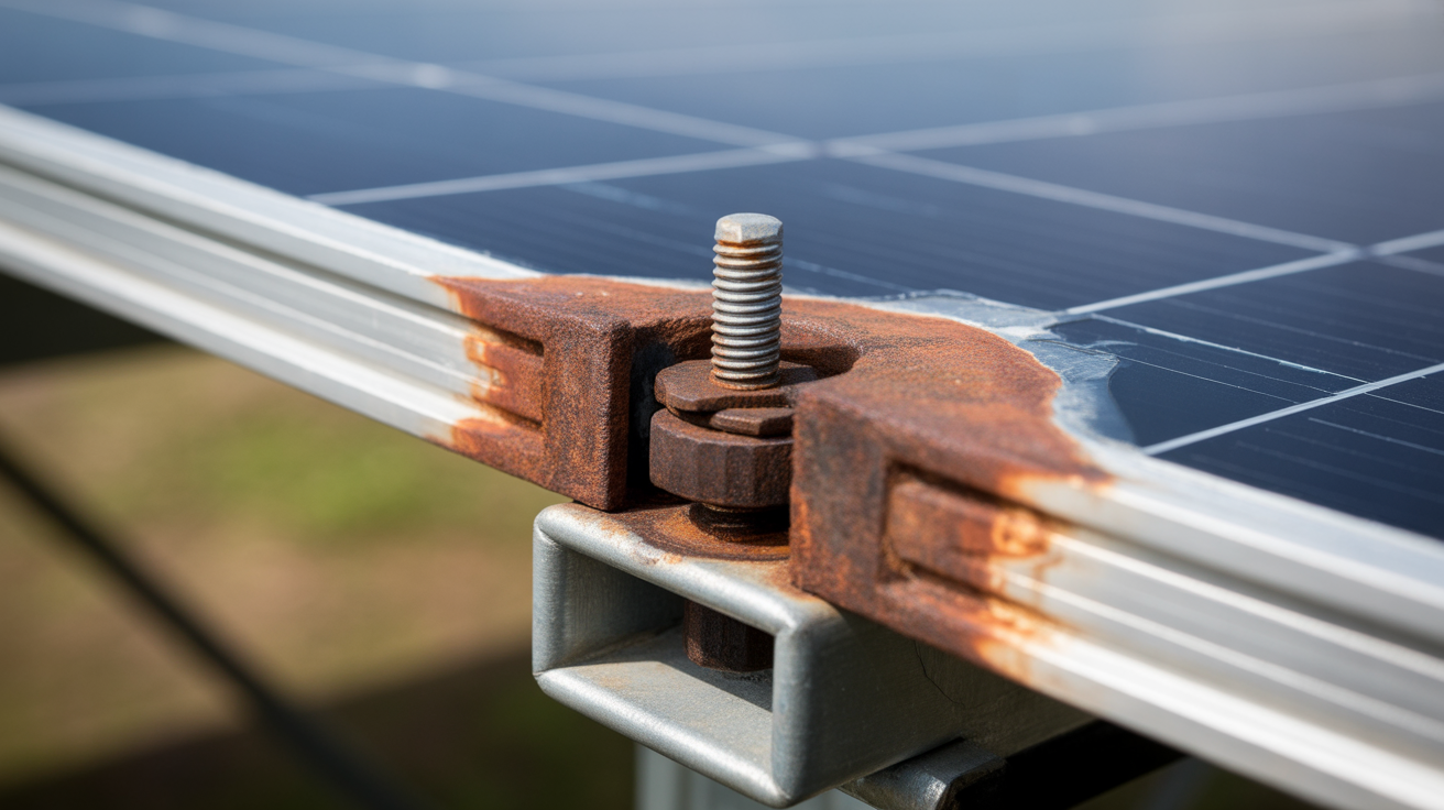
Corrosion is the primary enemy of electrical connections. In coastal areas, salt-laden air creates a highly conductive electrolyte that dramatically accelerates galvanic corrosion, especially between dissimilar metals like copper grounding conductors and aluminum racking. High humidity and industrial pollutants containing sulfur or other chemicals create a similarly corrosive environment. This corrosion introduces high resistance into the bonding path, which can prevent overcurrent protection devices from operating during a fault, turning the entire array into a shock hazard.
Thermal Cycling and Mechanical Stress
Locations with wide diurnal temperature ranges, such as deserts, subject every component to constant expansion and contraction. This thermal cycling can cause mechanical fasteners, including the bolts and lugs used for bonding, to loosen over time. A connection that was perfectly torqued during installation can become a high-resistance point after thousands of cycles. This gradual loosening is a silent failure mode that often goes undetected until a fault occurs or a maintenance check is performed.
The Impact of Moisture and Soil Conditions
Persistent moisture and challenging soil conditions directly impact the effectiveness of the grounding electrode system. Frozen or dry, sandy soil exhibits high resistivity, which can impede the dissipation of fault currents into the earth. Furthermore, water ingress into conduits and junction boxes can compromise connections and accelerate corrosion from the inside out. As research from the IEA points out, many large-scale solar projects are built on land with limited alternative uses, such as arid regions or former industrial sites. A study, Solar Energy Perspectives, notes that considerable potential for solar development rests in these challenging environments, making robust design a necessity.
Identifying and Understanding Rack Mis-bonding
Proper bonding creates a single, continuous, low-impedance path that connects all metallic components of the PV array. This ensures that in the event of an electrical fault, the current has a safe and effective path to ground, allowing breakers to trip as designed. Mis-bonding negates this protection.

Common Causes of Mis-bonding in the Field
Failures in the field often trace back to a few common installation errors that are exacerbated by harsh conditions:
- Improper Hardware: Using generic steel hardware that rusts or relying on star washers that lose tension over time. These components are not designed to maintain consistent bonding force through years of thermal cycling and exposure to corrosive elements.
- Surface Contamination: Aluminum racking and module frames are typically covered with a non-conductive anodized layer for protection. Failure to penetrate this layer with listed bonding hardware or to abrade the surface at connection points results in a weak or non-existent electrical bond.
- Incorrect Torque: Both under- and over-torquing connections are problematic. Under-torqued bolts are loose from day one, while over-torquing can damage the hardware or the rack, leading to a failure down the line.
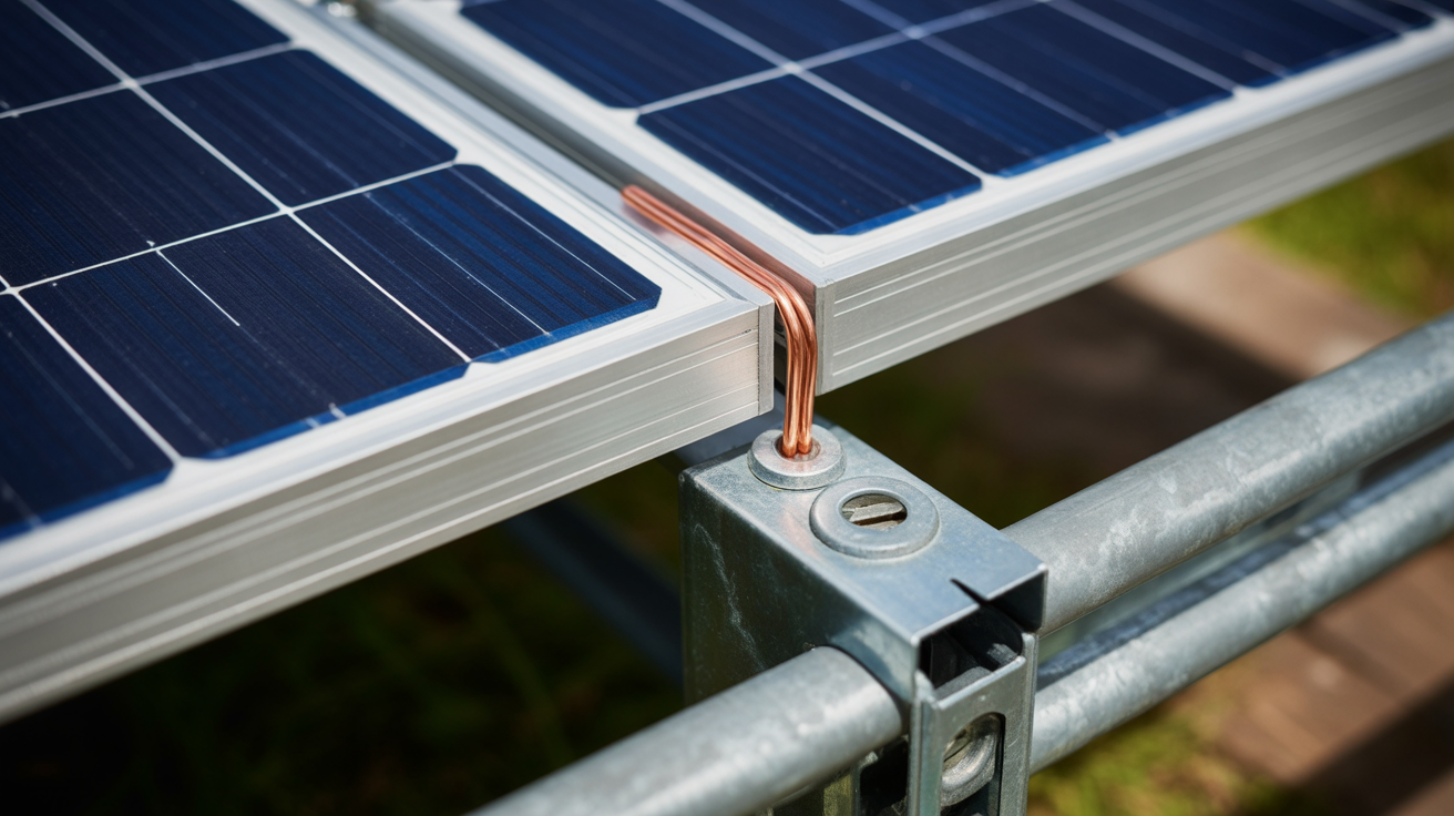
- Material Incompatibility: Directly connecting a copper grounding conductor to an aluminum rack without proper precautions (like using tin-plated lugs and antioxidant compounds) creates a perfect scenario for galvanic corrosion.
Best Practices for Durable PV Earthing in Extreme Environments
Building a resilient earthing system for harsh climates requires a methodical approach focused on materials, preparation, and installation technique.
Material Selection and Corrosion Prevention
The first line of defense is choosing the right materials. Use stainless steel (304 or, for coastal areas, 316) or appropriately coated hardware designed for outdoor and corrosive environments. Utilize bonding hardware, such as lay-in lugs or specialized clips, that is specifically listed for the racking system you are using. When connecting copper to aluminum, always use a tin-plated lug and apply an antioxidant compound to the contact surfaces to inhibit moisture and oxygen, preventing corrosion.
Ensuring Mechanical and Electrical Integrity
A reliable bond is both mechanically secure and electrically sound. Follow these critical steps:
- Surface Preparation: Never assume a bolt will create a bond. Use listed bonding hardware that is designed to pierce anodized coatings or abrade the surface to create a direct metal-to-metal connection.
- Proper Torque: Always use a calibrated torque wrench. Follow the manufacturer's specifications for every single connection. A simple torque mark with a paint pen provides a quick visual check for quality control.
- System Redundancy: Where practical, use multiple bonding points. Run a dedicated equipment grounding conductor (EGC) to connect rows of racking, rather than relying solely on the mechanical connections of the racking itself to carry fault currents over long distances.
Verification and Maintenance Strategies
Trust, but verify. A robust quality assurance process during commissioning and a scheduled maintenance plan are essential for long-term reliability, especially in challenging environments.
Commissioning Tests You Cannot Skip
Visual inspection is not enough. Use a Digital Low-Resistance Ohmmeter (DLRO) to perform continuity tests from various points on the array (like the farthest module frame) back to the grounding electrode conductor. This measurement, typically requiring a resistance of just a few milliohms, is the only way to confirm a high-quality, low-impedance bonding path exists. This aligns with the broader industry need for grid stability, as a poor earthing system can affect how a plant behaves during a grid disturbance. As the IEA's report Getting Wind and Solar onto the Grid explains, grid codes have evolved to require power plants to remain connected during voltage dips, a capability that relies on proper fault detection underpinned by a solid grounding system.
Long-Term Maintenance for Reliability
For systems in harsh climates, create a maintenance plan that includes periodic inspections of the earthing system. This should happen annually in the most severe locations, such as coastal or heavy industrial sites. During these inspections, visually check for corrosion, physically check for loose connections, and consider performing random torque checks and DLRO measurements to catch problems before they lead to a critical failure.
Wrapping Up: Building Resilient Systems
The challenges posed by harsh climates on PV earthing systems are significant but entirely manageable with the right knowledge and attention to detail. Moving beyond standard practices to adopt a methodology rooted in superior material selection, meticulous surface preparation, precise installation techniques, and thorough verification is key. A well-designed and properly installed earthing system is not merely about code compliance; it is a fundamental investment in the safety, long-term reliability, and financial performance of the entire solar energy asset.
Frequently Asked Questions
Can I rely on the module frame's anodized coating for protection?
The coating provides excellent corrosion protection, but it is an electrical insulator. This coating must be properly penetrated or removed at all bonding points. Use hardware specifically listed for bonding, such as clips or washers with specialized teeth, to ensure a reliable and lasting electrical connection is made directly to the metal frame.
Are star washers a good solution for bonding?
While star washers can bite through a coating, they are not a reliable long-term solution for bonding in PV systems. They are prone to corrosion and can lose tension over time due to thermal cycling, which can lead to a high-resistance connection. It is always better to use hardware that is specifically designed and listed for bonding PV modules and racking systems.
How often should I inspect grounding connections in a coastal area?
In highly corrosive environments like coastal or industrial zones, an annual inspection is a recommended best practice. This inspection should include thorough visual checks for any signs of corrosion and random torque checks on critical mechanical connections to confirm they remain secure and have not loosened over time.
What is the main difference between grounding and bonding?
Bonding is the process of connecting all the metallic parts of a system that are not meant to carry current, such as racks and module frames, to create a single, continuous electrical path. Grounding is the act of connecting this bonded system to the earth, typically via a grounding electrode like a ground rod. Bonding gives fault current a safe path to follow, while grounding helps to safely dissipate that current into the earth and stabilize the system's voltage.


Leave a comment
All comments are moderated before being published.
This site is protected by hCaptcha and the hCaptcha Privacy Policy and Terms of Service apply.